COMMISSIONING
Carry out functional checks
to prove the operation of interlocks/inter-tripping between the 415 Volts
incoming and bus coupler breakers in each switchboard & MCC.
Carry out functional checks
to prove the operation of interlock and inter tripping between the 11 KV
upstream and 415 Volts circuit breaker wherever required.
GENERAL CHECKS:
Inspect any physical damage in the bus bar,
insulation, panel doors, power & sliding contacts etc. And to be rectified if found and make
individual unit ready for commissioning.
Making the panel inside dust free & free
from foreign materials.
Checking the tightness alignment & clearance
of bus bars ,smooth ness in racking in & racking out of modules, proper
making of sliding contacts, tightness of input power cables and module power
control o/ps & control internal wire connection.
Inspect all contacts , relays and make sure that any blocking used
for shipping purpose is removed. This is a must check before commissioning .
Check all doors for proper mounting with respect
to the switch handle.
Check door interlock mechanism.
Test the pts,cts &
relays involved. Keep the recommended settings for the relays like over-current,
under-voltage & overload protections, calibrate the meters (ammeters,
voltmeters, power meters & energy meters etc)
Test the insulation of boards with 500 v dc megger & the value
should be as per the relevant is specification (more than 5 mega ohms)
Check closing &
tripping interlocks , overload release setting of all air circuit breakers in
the panel.
Check the protection
circuit wiring connections by conducting primary injection current
Check the input power cable terminations from
transformer secondary
Ensure the phase sequence and ct links are proper
before charging the panel.
check closing &
tripping mechanism operates smoothly both manually and electrically
Space heaters &
thermostat shall be in good and running condition.
Energising checks
Check that communications have been established between
11 KV
switchgear,415 Volts switchgear and the UCB. Also check the safety
clearance available before charging.
Ensure that the 11 KV and
415 Volts circuit breakers for charging are in isolated position. Also tie
breakers between Emergency switchboard No-1 and bus coupler breaker at unit
service switchboard No-1 are OFF and isolated.
Ensure that the 415 volts
V.T.s for Section A & B are in position and
fuses in service.
Ensure that all the
outgoing feeder breakers, contactors and Isolators of 415 Volts switchgear are
off and isolated.
Ensure that the control
circuit fuses for 11 KV and 415 volts circuit breakers for the power
transformers and those for the 415 volts buscoupler breaker of switchboard are
put on.
Ensure that protection
relay settings are correct for feeder VCBs at HT switchgear and incomers at LT
switchgear.
ENERGISING PROCEDURE:
Energise the 415 volts switchgear control circuit bus from its normal source of supply.
Put the 415 volts circuit breaker(Incomer 1) in test position with selector switch in LOCAL.
Close and open the breaker from local and check that the status
indications are correct.
Carry out the tests for the next Incomer and buscoupler for the same LT Switchgear.
Put the 11 KV breaker for power transformer - A in test position
with the selector switch to interlock ‘OUT” position.
Close and open the 11 KV breaker from local and check status indications are correct.
Put the selector switch to interlock IN and close and open the
breaker from UCB and check that status indications
are correct.
Carry out the tests for 11
KV breaker Transformer – B.
Put the 11 KV breaker
transformer A in service position with
the selector switch to interlock ‘IN’ position.
Close the 11 KV breaker
from UCB to first energise the Power Transformer A.
Open and close the 11 KV
breaker
Note the ammeter for the
transformer H.V side for any abnormal current. Check the transformer externally for any abnormality.
If 8.3.13 ( bus coupler
breakers )is O.K.,put the 415 Volts breaker (Incomer 1) for Transformer A in SERVICE position with the selector switch in REMOTE.
Close the 415 Volts Incomer
1 breaker from UCB to first energise the section A of LT switchboard.
Check the ammeter and voltmeter reading and noted in the register.
voltage relays are in
picked up(energised) condition. Check
phase rotation.
Check externally for any
abnormality with the 415 Volts LT
switchboard.
Initiate tripping through
overcurrent relay on the 11 KV side and
check that both the 11 KV and 415 Volts
breakers of the power transformer A trip.
Put the 415 Volts bus coupler breaker for LT switchgear in
SERVICE position with the selector
switch in ‘REMOTE’
Close the 11 KV and 415
Volts breakers(Incomer 2) for power
transformer B in “TEST” position
Close the 415 volts bus coupler
breaker from UCB to first energise the
section B of the LT switchgear
Note the ammeter in
incomer-A panel for any abnormal current.
Also note the voltmeter in bus section B for
correct bus voltages.
Check that the under voltage
relays in section B are in energised condition.
Check externally for any
abnormality with the 415 Volts in bus
section B
Switch off the bus coupler
breaker
Put the 11 KV breaker for power transformer B in ‘SERVICE’ position
with its selector switch to interlock
‘IN’.
Close the 11 KV breaker for
power transformer B from UCB to first
energise the transformer.
Open and reclose the 11
KV breaker
Note the ammeter on the 11
KV side of the transformer for any
abnormal current
Check externally for any
abnormality with the transformer.
Put the 415 Volts breaker(Incomer 2) for Transformer B in
SERVICE position
with its selector switches in ‘REMOTE’
Close the 415 volts breaker
for the transformer to energise the bus
section B
Note the ammeter and
voltmeter in bus section B for any
abnormal current and voltage.
Check phase rotation of B
section and phase in & phase out
between section A & B
If everything with the
transformers and the LT switchgear are
O.K. keep the transformers and the 415
volts bus energised for 24 hours.
After 24 hours check that
there is no abnormality with the
transformers and the 415 Volts LT switchgear.
Also check periodically bucholtz relay for
any chapped gas on in.
For MCCs & Aux. Control
panels ,Upstream breakers and
interconnecting cables will come into picture in stead of 11 KV outgoing feeder and power transformers.


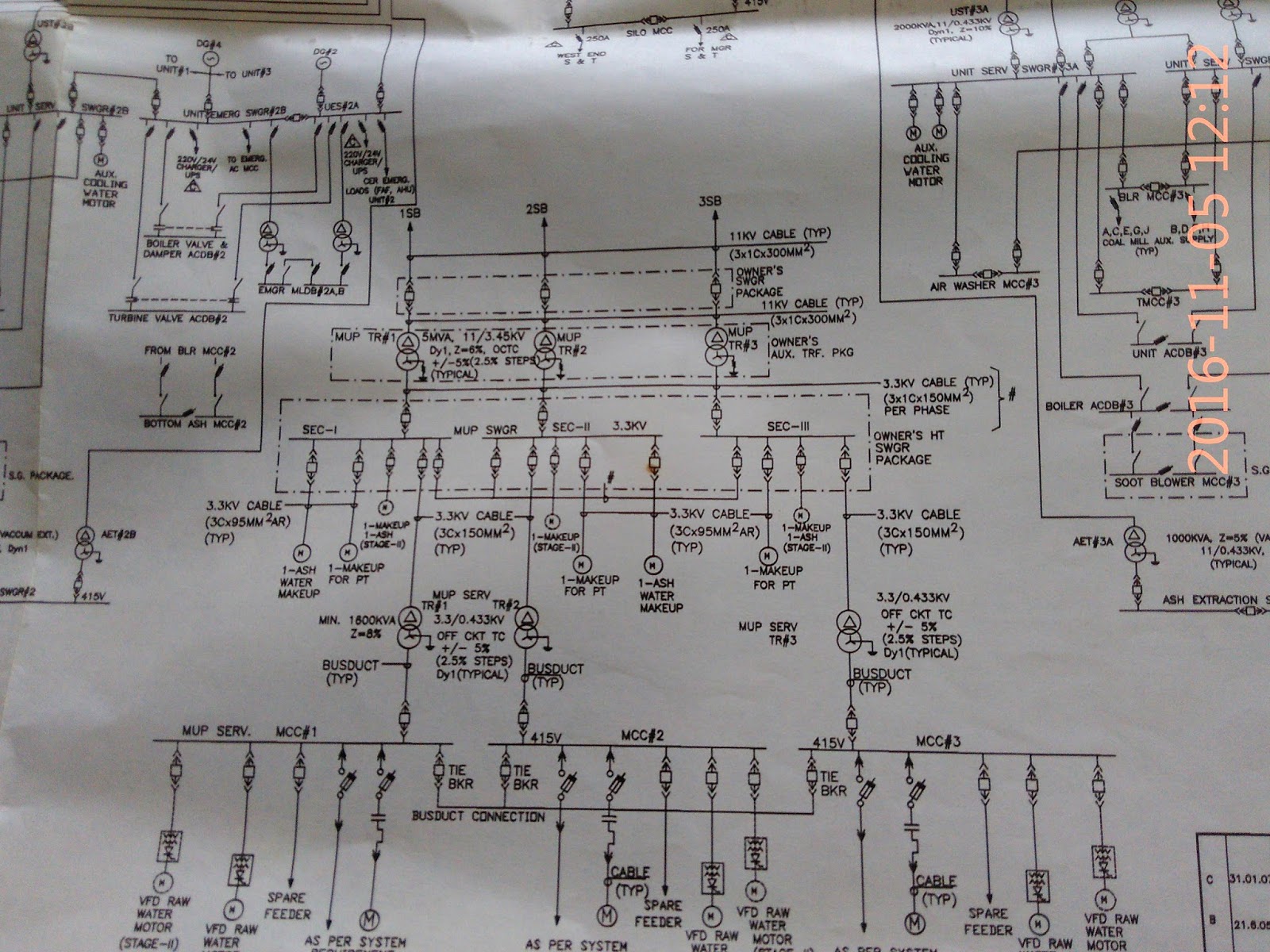

Few portion of SLD are given to understand the flow of power to different LTMCC.
wish all my readers happy new year 2017.


