Total Pageviews

Friday 27 September 2013

VISUAL INSPECTION OF CRITICAL PIPING -ABC OF THERMAL POWER STATION

Visual inspection


Visual inspection is most widely used NDE tool. It is simple widely used and can be
carried out quickly and cheaply. A specimen can be tested with different NDE process
but before carrying out any examination visual inspection to be carried out. A visual
inspection can reveal many things such as quality of weld, presence or absence of
cracks, surface porosity, misalignment etc. Basic principle of carrying out visual
inspection is to illuminate the weld area sufficiently to observe the defect. Visual
inspection can be carried out with many observation tools like mirror, telescope,

periscope and boroscope. 

Present day Boroscopic inspection is required to be carried out at different places
of thermal power station. A boroscope inspection is carried out in different headers,
tubes etc wherever easy access of visual inspection is not there. A modern day
Boroscopic instrument consist of light fibre optic cable, lenses etc to get the exact
visual of the weld area.
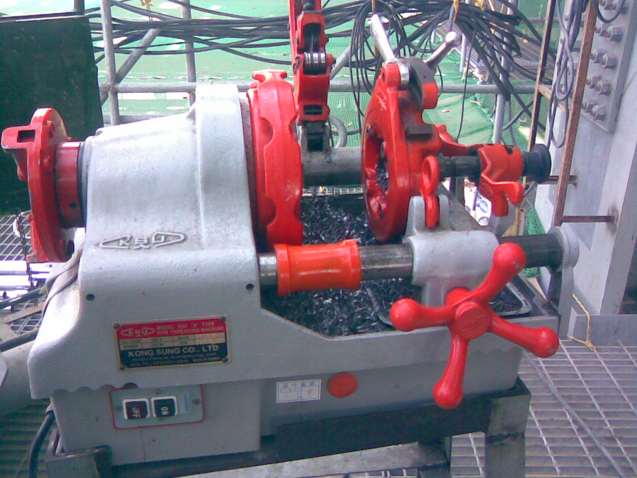
Different types of gauges are also available as aid for visual inspection. Theses
are Taper gauges, Hi-Lo gauges, Filler gauges and multipurpose gauges.
Before welding a few points needs the attention of site engineers.
1. Review of drawings and specification.
2. Check the qualification of personnel and procedures.
3. Check the alignment /fit up of weld joints.
4. Follow WPS and Field Quality Plan
5. Surface cleanness of the weld.
Welding Procedure (WPS)
-        It should ensure correct welding procedure is employed.
-        Welding procedure should be well documented considering all aspect of welding.
-        Prior to welding base material identification including cleanness to be checked.
-        For joint fit up one should check groove angle, Root Opening, Backing, etc.
During Welding following aspect needs to be checked.
Quality of Root bead to be checked.
Joint Root preparation before the welding second side.
Preheat and inter pass temperature.
Sequence of weld Pass.
Inter Pass Cleaning
After Welding Following points need to be checked. 
Final weld appearance, Final weld Size.
Weld length, Dimensional accuracy, amount of distortion,
Post heating and Post weld heat treatment, Checking Discontinuity.
Following Discontinuities are generally present in the weld.
Porosity, Incomplete /lack of fusion, Incomplete Joint penetration, Undercut,
Overlap, Cracks, Slag inclusion, Excess Reinforcement etc.
While code permits limited number of such discontinuities. But discontinuities listed
Below are never allowed.
Cracks and incomplete fusion.
Undercut, overlap and improper contour results in stress raiser
One of the important aspects is illumination during visual inspection. Some codes specify
16 lux for general inspection and 54 lux for discontinuities.


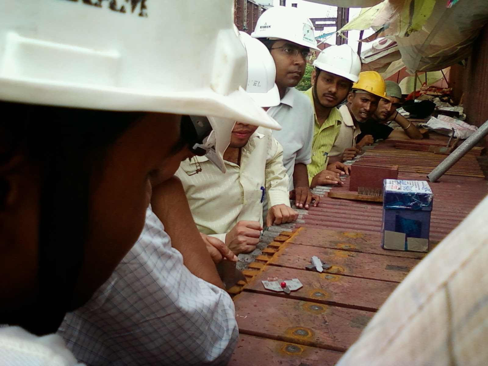
Welding training is going on both at class room and at site with welding gauge by welding

experts from NDE examination.

P.S If  you are looking to earn few legitimate extra money from the comfort of your home then please click on the link given below

LINK 1 - PLEASE CLICK HERE 
LINK 2 - PLEASE CLICK HERE

Tuesday 17 September 2013

BASICS OF CRITICAL PIPING ERECTION IN A THERMAL POWER STATION PART IV

This is the final part of the basics of piping a construction worker ought to know beside his

own piping job. Knowing these basics will help him in erection work .

- To classify nature of flow we use Reynold’s number. It is dimension less and laminar

   flow has 2100 value.

- To ensure that the stresses in Piping component is within the limit we carry out stress

   analysis. Now a day different software is available to carry out the job and one of the
   software used   is CEASER.

- There are different types of stresses generated within the pipe line. The names are

   (i) Axial stresses ( Tensile /compressive) (ii) Shear stresses (iii) Radial stresses
   (iv) Hoopes  stresses.
- The  static loads on the pipes are pressure , dead weight pipes and attachment and
   load due to thermal expansion.
- Dynamic loads are wind ,wave ,earthquake and water hammering.
- Stress developed due to thermal expansion = E * e/L ; where as E= Young’s modulous ,
  e= Increase in length due to thermal expansion and L = total length of pipe.
- Variable load and constant load spring hangers.
                 Variables use coiled springs to support a load and allow movement. The
  resistance of the coil to a load changes during compression, which is why these devices
  are called "variables". Constant Spring Hanger provides constant support force for
  pipes and equipment subjected to vertical movement due to thermal expansion at
  locations where maintaining a constant stress is critical.
Static loads are those which are applied slowly enough    that the system has 
   time to react and internally distribute the loads, thus remaining in equilibrium


- Dynamic load -a load changes very quickly with time . The piping system may not have time
  to internally distribute the loads , so forces and moments are not always resolved.
 One of the welding stations used in piping and other erection jobs like boiler ,turbine ,CHP etc.


 Small tools  used for pipe cutting and threading for small bore        piping


P.S If  you are looking to earn few legitimate extra money from the comfort of your home then please click on the link given below

LINK 1 - PLEASE CLICK HERE 
LINK 2 - PLEASE CLICK HERE


Sunday 8 September 2013

BASICS OF PIPING ERECTION IN THERMAL POWER STATION. PART -II


- In an isometric drawing of Piping following points may be looked into.

- BOM ( Bill of Material) , Pipe routing with General Arrangement Drawing , Supporting

  arrangement , Hydro test Pressure , Provision of drains and vents etc.

- All of the pipes will come in pieces and stubs are welded on it. The same is to be either

  pre-assembled or erected and assembled at site. When fluid is gas , steam or air connection

  will be from top and in case of water or fuel the connection will be at the bottom. This

  type of arrangement is being followed in general.

- We provide high point vent to remove air from the pipeline and low point drain to remove

   condensate or liquid after hydro test.

- When there is rise of  steam pipeline against the flow of pipelines we provide drip leg to remove

   condensate from the pipeline .This is to avoid water hammering in the pipe line .

- Steam lines with following lines come under the purview of Indian Boiler Regulation.

   line for which design pressure is > 3.5 kg/cm2 .

   line size above 10" with one 1.0 Kg/cm2 pressure.

- Normal upstream and down stream length required for an orifice flow meter is 15D

  and 5D respectively.

- The thumb rule of two consecutive  butt weld id  1D.

- Following hardness test are followed at site.

- Rockwell hardness test , Brinell Hardness test and Vickers hardness test.

- At site we carry out DE and NDE test. DE means destructive test such as bend test ,

  Impact and hardness test. NDE means non-destructive test such as Radiography ,

  Ultrasonic , Dye penetration test and Magnetic penetration test.

- In general Hydro test pressure is 1.5 times design pressure of the system.

  For design temperature above the test temperature minimum test pressure can be

  calculated as follows :-

  P( test) = ( 1.5 * P* St)/ S

  where P(test) = Minimum test Pressure ; P = internal design pressure.

  St = Allowable stress at test temperature  ; S =  Allowable stress at design temperature.

- Stress Analysis now a days are carried out through a software . Stress analysis is done

  at design stage to ensure that piping system stress is within limit and to solve dynamic

  problem like mechanical vibration , pulsation , fluid hammer etc. Stress analysis is also

  done to solve problems associated with temperature. This is designer domain and site

  never does it therefore only a glimpse is given.

- Name of the few stresses are Axial stresses ( Tensile/ Comprehensive) , Shear Stresses ,

  Radial Stresses and Hoopes Stresses.

- Stress formula due to thermal expansion is

  stress developed - E * e/L ; E= Young' modulus ; e = Increase in length due to thermal

  expansion  ; L = original length of pipe.

- For calculating thermal expansion following formula is used.

  E (expansion) = Co-efficient of expansion * L ( length of Pipe)* T ( temp differential).

- One of the major work of stress analysis is to locate hanger supports and anchor points.

  For calculating that different loads are considered ( primary loads , secondary loads and

  occasional loads ).

- Site has to locate the hanger accurately at the place marked in the drawing. Any displacement

  form the designed location due to interference should  promptly be reported to designer for his

  acceptance . He can do analysis and confirm about displacement. Number of instances known

  to me about failure in piping system due to above. All site engineer should  be cautious in this

 area.

-Pipe strain may distort the alignment of rotating equipment . Therefore it is customary

 before welding the last joint with the machine freeness of pipes has been checked with

 all supports are on line . This we did in case of Boiler Feed Pump and Turbines. Welding

 will not start until and unless competent authority checks the freeness.


continued for next part.


P.S If  you are looking to earn few legitimate extra money from the comfort of your home then please click on the link given below

LINK 1 - PLEASE CLICK HERE 
LINK 2 - PLEASE CLICK HERE


BASICS OF PIPING ERECTION IN A THERMAL POWER STATION.

In my last dispatch the scope of critical piping and LP piping has been covered. Beside

these piping there are piping also covered under different packages ( Boiler ,Turbine ,

ash handling , DM plant ,Fire fighting ,cooling Tower etc). IBR piping is only covered

in Boiler and Turbine . Rest of the package includes LP piping only.

Therefore my discussion on basics will be mostly based on high pressure piping and LP

piping available in Boiler and Turbine.


- The codes we are following in piping is IBR and ASME 31.5.

- Different structural materials like ISMB, ISA ,ISMC ,ISWB etc are used for supports.

 Meaning of the same and sizes are available any standard handbook of structures.

- For branching one size lesser  of run pipe stub on is preferred . For branching other than

  one size of run pipes stub in is preferred. This is as per ASME 31.3.

- Pipe is identified by NB and thickness is defined by schedules whereas tube is identified

  as OD.

- However from 14" size pipe NB =OD .

- Soluble Dam is a water soluble material used for  restricting the purging  gas within the

  pipe. This material are extensive used where purging with inert gas is recommended during

  welding. This reduces the requirement of Argon gas ( used as purged gas at site)

- In piping two types bolt are used . One is machine bolt ( having one side head and other

  side nut ) and other is stud bolt ( having nut in both sides).

- One has to start learning about the isometric drawing of pipe line and mark all the

  elevation . Sometimes one side elevation and slope ratio is given other side elevation

  to be calculated. this will help during the erection.

- Long radius elbow means 1.5D where D is the diameter of pipe.

- Normally eccentric reducer is used in pump suction and concentric reducer is used in

  pump discharge.

- Follow IBR /ASTM  code for pipe fittings ,flanges etc.

- Thumb rule for spanner sizing is 1.5 * Diameter of the bolt.

- Thumb rule for current requirement is diameter of electrode * 40 +/- 20.

-  Steam tracing are used in HFO ( heavy fuel oil) line to increase pump ability of fluid.

   It is placed over the pipe all along the line and connected with different station with

   steam traps and valves to discharge condensate time to time.

-  Items like control valves , orifice plates , rota meter etc are removed during hydro test ,

    mass flushing  and  replaced by spool pieces of same diameter of pipe. Therefore these

    pieces are fabricated before hand.

- We provide dampener  in the piping of reciprocating pump to reduce pulsation.

- Use of correct type of reducer in pump suction is absolutely necessary to reduce

   cavitation of PUMP. Also knowledge of NP SH ( Net pump suction head ) will give

   an idea.


continued for next part


P.S If  you are looking to earn few legitimate extra money from the comfort of your home then please click on the link given below

LINK 1 - PLEASE CLICK HERE 
LINK 2 - PLEASE CLICK HERE


Tuesday 3 September 2013

CRITICAL PIPING AND LP PIPING ERECTION - ABC OF THERMAL POWER STATION

Till last blog I have tried to explain basics of thermal power stations including enviormental

requirement , land requirement , soil testing , other aspect of information required initially for

civil design , discussed about civil works requirement ,fabrication and erection of structural

items , Boiler and its auxiliaries erection, ESP erection and a brief on commissioning of ESP.

In 107 blogs above aspects were covered . I am writing the blog for new comers to construction

field so that they will have an idea about a power station. I received number of mails on my

mails from different sources i.e students , newly appointed construction people etc and I tried

my best to answer their questions . I learn a lot from their questions and I do hope all the readers

will participate in question and answer on the topics.

Today I will start to discuss about critical piping and LP piping of a thermal power station.

Piping involves lot of welding ,NDE , pre heating ,post heating ,stress relieving etc and its

a vast subject to cover. However my endeavour will be to give basic knowledge required for

piping erection.

-Critical Piping scope covers following work in general-

-Complete main steam, hot reheat & cold reheat piping between boiler and turbine nozzles,
HP bypass upstream & downstream piping and LP bypass upstream & downstream piping up
 to the condenser  inlet nozzles- as per P&ID finalised during the detailed engineering.


-Complete auxiliary PRDS & Aux. Steam piping system up to Terminal Point.


-Interconnection of Auxiliary steam piping with existing stage (s) as per scope indicated in tender

 drawing, along with necessary trestles.

-Spray piping system for the following , :
(1.)       Re heater attemperation,
(2.)       Super heater attemperation
(3.)       Auxiliary PRDS system


-Steam drains from piping /equipment(s) such as. flash Tank(s) / flash tank
  manifold(s) as per the scope .


 -  Miscellaneous line drains and vents.


- Complete safety valve exhaust piping for SVs / SRVs on piping/equipment .


The Scope of Low Pressure (LP) piping shall cover piping systems for the following services.
(a.)       Boiler fill system.
(b.)       Equipment Cooling Water (ECW) system including its chemical dosing system (both
primary and secondary)
(c.)      Service water cum CW blow down system
(d.)      Instrument Air System.
(e.)      Service (plant) Air System.
(f.)       Drain piping system for the piping\equipment etc.
(g.)      Tanks as described elsewhere in the specification for the above systems.
(h)        Air preheater wash water system
(i)         Re-circulation pipes along with valves, breakdown orificies etc.,


CONTINUED

P.S If  you are looking to earn few legitimate extra money from the comfort of your home then please click on the link given below

LINK 1 - PLEASE CLICK HERE 
LINK 2 - PLEASE CLICK HERE