Till last dispatch I have given an
outline of Turbine ,Generator erection
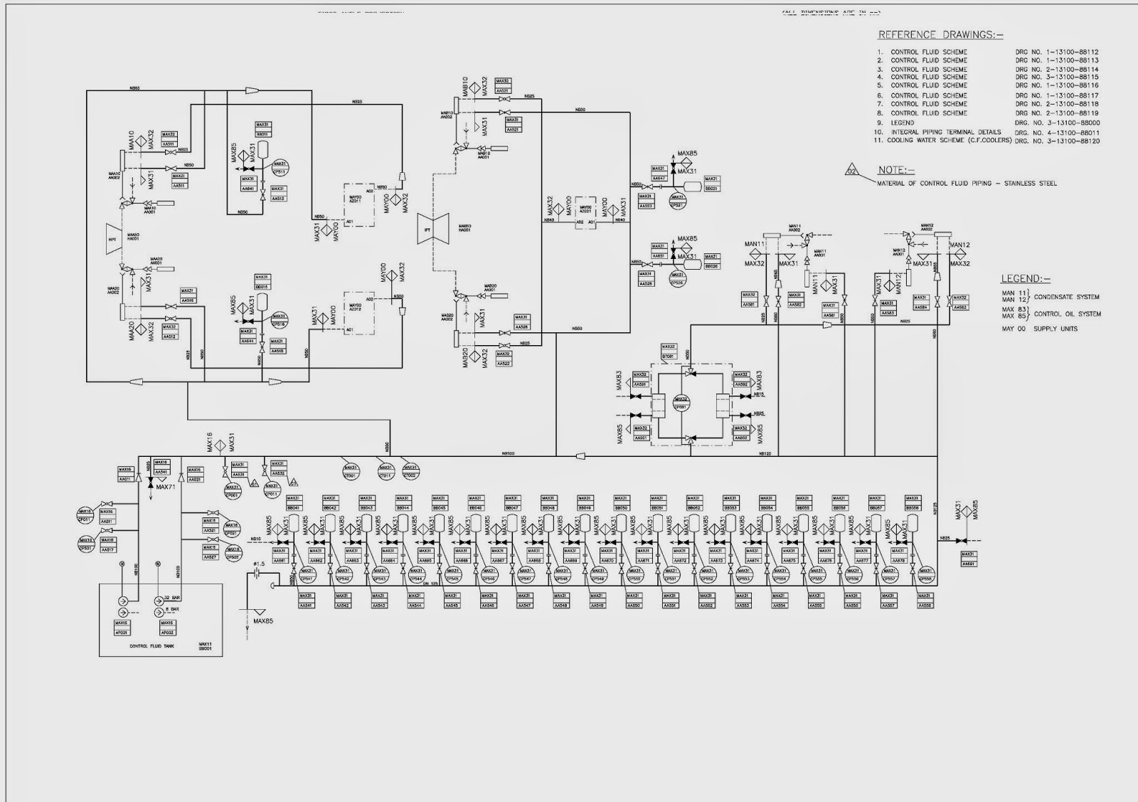
including some detail of integral
piping specially Lube oil ,control oil ,
drain lines ,seal steam lines etc. From
today onwards I will describe the major
auxiliaries likes Condenser , pumps and their drive turbines , heaters and
other items . I receive number of mails from supervisors and young engineers
for auxiliaries erection details therefore I will try to answer all their queries in my
subsequent dispatches.
In my working time I have come across
two distinct type of set one is Russian and other is German. For a given
capacity like 200 MW set Russian condenser work is very less compare to German
condenser. Russian condensers are pre- fabricated up to tube supporting plate and box has to
inserted and assembled . However for German design set like KWU /Siemens every
item needs to be assembled i.e. starting from base assembly to the making of
the box therefore time taken for
condenser erection is more than Russian set. I have never worked in Chinese
sets therefore feedback is not available with me. I request readers to
enlighten me in this regard. One more recent development in 660MW Siemens deign
the base plate is tilled half a degree and instead of spring support bearings
are provided below the base plate. There may be some other changes but not that
significant during erection.
I will outline my discussion based on
BHEL make 500MW. However I will use photographs of 660 MW set so readers should
not get confused about the size.
The condenser is a box type construction with divided water box design double flow; two pass
which facilitates the operation of one half of the condenser while other half is under maintenance.
The steam space is of rectangular cross-section with integral air-cooling section from where air and non–condensable gases are drawn out with the help of air evacuation equipment.
The surface condenser is mounted on
spring supports. The condenser is welded with
the exhaust hood of the low-pressure turbine. The tube plates are welded
with the water chambers. Condensers are provided with domed shape water box.
The condenser tubes are supported within the condenser shell by tube support
plates. The condenser is installed in such a way that all condenser tubes are
drained automatically into the condenser water Condition has been provided with an extension suitably
to connect it to the turbine exhaust opening. Adequate internal clearance is
provided. The rigid construction results in a sound-condenser combination for
trouble free operation.
The water boxes of the condenser have
been designed for smooth entry and uniform distribution of cooling water to all
the tubes. The water boxes are removable type and have been provided with
necessary hinged manholes for easy access to the interior for inspection. Each
water box has been provided with a vent and drain connection. The circulating water
connections of adequate size have been provided with water boxes. The
condensate produced in the condenser & drains entering through flash
vessels collect in the hot well from where the pass to the condensate pumps.

CONTINUED PART -II
P.S If you are looking to earn few extra money from the comfort of your home then please click on the link given below
LINK 1 - PLEASE CLICK HERE
LINK 2 - PLEASE CLICK HERE
P.S If you are looking to earn few extra money from the comfort of your home then please click on the link given below
LINK 1 - PLEASE CLICK HERE
LINK 2 - PLEASE CLICK HERE