Part –IV
Once all the physical checks are over
and shuttering has been removed then we can proceed for Ultrasonic Testing of
foundation. This procedure is not followed in India at the beginning but if
there is problem in casting then this is the only way to find out honeycomb in
the concrete. But I strongly feel that such testing to be done at the very
beginning and before the start of Mechanical Erection. In most of the cases
civil works comes under the scope of customer and mechanical works are done by
some other vendor. When problem arise at later date then it is very difficult
to analyse the problem due to lack of scientific data . If ultrasonic test is
carried out and found acceptable then one major side can be eliminated.
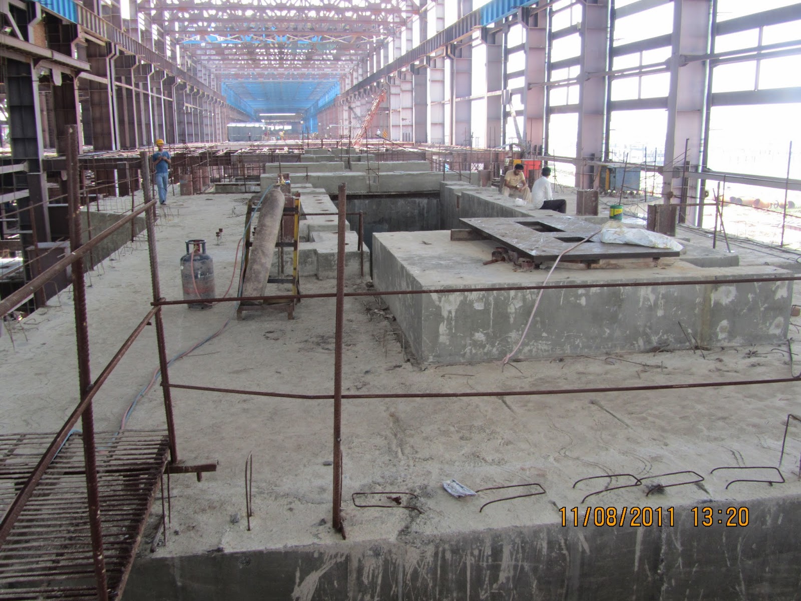
PREPARATION OF FOUNDATION FOR PLACEMENT
OF PEDESTALS AND BASE PLATES.
Foundation are to be cleaned and
loose concrete are to be chipped off.
Maintain elevation of foundation to
ensure correct thickness of non-shrink grout.
A reference point for elevation in respect of
machine centre line (equivalent to LP rear pedestal) is to be maintained at a proper place. This point is to be preserved with proper protection. For making
reference point a one side ground plate of about 200 x300 x20 mm may be used. This may be welded on a I-beam near Generator. The ground position of the plate is to be kept on top side and all elevation are to be transferred from this point with the help of water level jar or by instrument like total station, dumpy level . A correct elevation reading is to be punched on this plate. This reference point is to be used only during the turbine erection period. (this is an alternative procedure earlier discussed)
Clean and de burr piping sleeves of
the foundation on ID/OD of the pipe.
Ensure all corners of the foundation
remains perfect during chipping of extra concrete of foundation.
PLACEMENT OF PEDESTALS
Open the package and clean the
pedestal.
Ensure there is no paint/oil/grease on bottom face of the pedestal sole plate.
Ensure there is no paint on inside
surface or the pedestal and if required sand blasting may be carried out at
site.
Ensure correct fitting/clearance of
locating rings of LP rear pedestal.
The half bore error of pedestals is punched by
manufacturing unit however in case it is not there, measure and punch half bore error of pedestal in left/right side of the pedestal. If the error is nil then this may be punched as zero-zero.
Ensure that the pedestal parting
plane is feeler tight after tightening all the parting plane bolts. If
required, colour matching may be carried out but scraping/cutting is to be done
on upper half cover only.
Check proper colour contact of
spherical/cylindrical supports of the bearing with the pedestal.
Check contact between spherical Torus
piece of bearing and spherical/cylindrical seat. In case of any variation in
contact no scraping/cutting to be carried out at site and this may be referred
to manufacturing unit. Check centreing of individual bearing w.r.t. pedestal
seal bores by fixing piano wire as stated earlier.
Ensure cleanliness of all pedestal
oil lines. Close opening of oil lines of pedestal to avoid any foreign material
entering in these pipe lines during erection at site.
Weld MOP suction and discharge pipe
lines in HP front pedestal as per the drawing before placement.
Assemble protection sheet in the
foundation bolt holes of pedestals.
Assemble anchor bolts along with anchor plate of
the pedestals. Ensure that there is good contact available to the backing plate with the foundation. If required colour matching/grinding may be carried out to achieve the contact.
Assemble protection sheet in the
anchor bolt hole from bottom side of HP rear pedestal foundation to avoid entry
of grout metal.
Ensure level of both anchor plate of
H.P. rear pedestal with 70-90 mm gap for filling of grouting concrete.
Adjust height of the Anchor Bolts as
specified in the drawing.

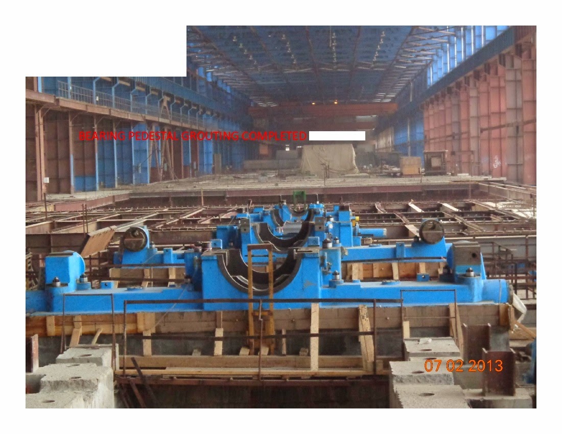
Picture of placement of Bearing pedestal for 660MW turbine.