For critical Piping and Large LP
piping are very important areas of thermal Power Station .
Erection of the
piping starts around 16 -18 months from Zero date
( Project Zero date) and
continues up to 32 to 35 months for a super thermal power project.
It has been observed that all
critical materials and their accessories were imported from developed countries because of their material composition. New material are introduced
to reduce the overall weight of the package in turn it will reduce the structure weight
(sizing) ,hanger sizes etc.
Because of that, restriction on
welding are imposed . One has to follow Welding
Procedure Sheet given by OEM in
totality . No compromise should be made.
Otherwise bigger problem will be crop
up in coming days. Now for this welding you
require different consumables
starting from filler wire, welding electrode
( 2.5 ,3.15,4 mm) , gases specially argon , and many other items
required during
welding. Most of the items are available in India but electrode
and filler wire may
not be available at the time of crisis. It is advisable to calculate the requirement
before hand and
keep checking the stock available . This is
true for critical piping area only.

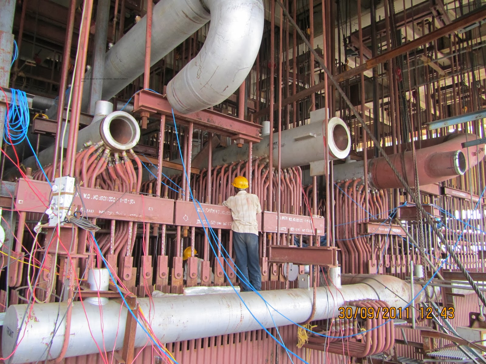
Following
sizes of pipes are generally used in a super thermal power station.
Few pictures of weld held is given below for information.

All the critical piping drawings
to be taken and mark the joint number as per code followed
at site. Calculate
the requirement of filler rod ( including wastage ) and welding electrode
different sizes. This will give fair amount of idea about the requirement.
Always check the straight and
associated fitting specially internal Diameter. Piping
vendor may source it
from different countries . There are developed countries
who may not be
Following ASME or IBR code . Error happens may be very less but it
comes out at
later date and there will be no time for fresh procurement . The project
will
suffer for that.
Please also verify the availability
of Test material ( welder test) at your disposal.
You need few materials to
qualify your HP welder in P91 /P22 etc both pipe and tube.
A concept of orbital welding is
now getting popular in India. This type of welding is being followed in
developed countries at site but in India the same is limited to manufacturing unit
only.
A short description of Orbital
welding is given below .
Orbital
welding uses the gas tungsten arc welding (GTAW) process as the source of the
electric arc that melts the base material and forms the weld. In the GTAW
process, an electric arc in established between a tungsten electrode and the
part to be welded. To start the arc, a high-voltage signal is used to break
down (ionize) the insulating properties of the shield gas and make it
electrically conductive to pass through a tiny amount of current. A capacitor
dumps current into this electrical path, which reduces the arc voltage to a
level at which the power supply can then supply current for the arc. The power
supply responds to the demand and provides weld current to keep the arc
established. The metal to be welded is melted by the intense heat of the arc
and fuses together.
|
Sl No.
|
Base Metal
|
Dia.(mm)
|
Thickness(mm)
|
|
1.
|
SA182F22CL3
|
356
|
45
|
|
2.
|
SA335P12
|
356
|
45
|
|
3.
|
SA234WP12CL1
|
300
|
45
|
|
4.
|
SA182F12CL2
|
559
|
67.3
|
|
5.
|
SA106GC.C
|
559
|
67.3
|
|
6.
|
SA105
|
356
|
46.3
|
|
7.
|
SA 335P22
|
508
|
63.1
|
|
8.
|
SA182F12CL2
|
219
|
34
|
|
9.
|
SA335P12
|
219
|
34
|
|
10.
|
SA234WP12CL1
|
219
|
34
|
|
11.
|
SA234WP91
|
450
|
63.5
|
|
12.
|
SA335P91
|
457
|
63.5
|
|
13.
|
SA324WPC
|
500
|
63.1
|
|
14.
|
SA234P91
|
470
|
60
|
|
15.
|
SA234P91
|
89
|
15.5
|
|
16.
|
SA234P91
|
630
|
85
|
There are
many reasons for using orbital welding equipment. The ability to make high
quality, consistent welds repeatedly, at a speed close to the maximum weld
speed, offer many benefits to the user:
1.
Productivity. An orbital welding system will drastically outperform manual
welders, many times paying for the cost of the orbital equipment in a single
job.
2.
Quality. The quality of a weld created by an orbital welding system (with
the correct weld program) will be superior to that of manual welding. In
applications such as semiconductor or pharmaceutical tube welding, orbital welding
is the only means to reach the weld quality requirements.
3.
Consistency. Once a weld program has been established, an orbital welding
system can repeatedly perform the same weld hundreds of times, eliminating the
normal variability, inconsistencies, errors, and defects of manual welding.
4. Skill
level. Certified welders are increasingly hard to find. With orbital
welding equipment, you don't need a certified welding operator. All it takes is
a skilled mechanic with some weld training.
5.
Versatility. Orbital welding may be used in applications where a tube or pipe
to be welded cannot be rotated or where rotation of the part is not practical.
In addition, orbital welding may be used in applications where access space
restrictions limit the physical size of the welding device. Weld heads may be
used in rows of boiler tubing, where it would be difficult for a manual welder
to use a welding torch or view the weld joint.
P.S If you are looking to earn few legitimate extra money from the comfort of your home then please click on the link given below