Collecting and emitting Rapping System
Commissioning :
Geared motors :
- In case
of emitting electrode rapping system confirm that heating elements are properly
fixed.
- Confirm
glands are properly placed
- Insulators
are healthy, clean and rigid without crack.
- Confirm
the mechanical clearance for each rapping system and decouple the motor.
- Confirm
the tightness of motor terminated cables, proper earthing, proper dressing of
cables.
- Megger
the motor and record the IR value.
Measure the coil resistance and record. Confirm IR value is at least 1Mohm.
Otherwise heat the motor and till the IR value is satisfactory.
- Confirm
the local push button station control supply terminal are properly done.
- Energise
the concerned module and locally bump and confirm direction.
- If the
direction is reverse, correct the direction.
- Couple
and take trial run as per duty cycle of the motor to study the proper
hammering. If the hammering is in the centre of shock pad in case of collecting rapping system for all the hammers
and the hammer in the centre of shock beam in case of emitting rapping, stop the
rapping motors.
- Clear for
tack welding of all bolt and nuts of hammers etc.
- Commission
all the rapping motors of all fields as above.
Disconnecting switches
- Ensure
Insulators are healthy, clean and rigid
- HV bus
terminal and earth connections inside are tight.
- Operation
of moving blades with HV and HV and earth contact is smooth and proper.
- Copper
cable between moving arm and insulator head is properly connected. Each
disconnecting switch is provided with a danger plate and two external earth
connections to earth mat.
- Doors are
closed tightly
- Interlocks
provided at doors handles are working properly.
INSULATOR HOUSING
- Insulators
are clean, healthy and rigid
- Copper
tubes are straight and not loose
- Heating
elements are properly fixed
- Earthing
is proper
- Screw
legs and nuts for placement of alignment jigs are welded
- Doors are
closed tightly
- Interlocks
are working properly
- Each
insulator housing is provided with a danger plate and two external earth
connection to earth grid.
ELECTRICAL SYSTEM
High
voltage transformer rectifier (HVR) with electronic controller (EC) :
The transformer rectifier supplies the power for
particulate charging and collection. The basic function of EC is to feed the
precipitator with maximum power input under constant current regulation.
Whenever there is a flash between emitting and collecting electrodes, the EC
will sense the flash over and quickly react by bringing the input voltage to zero
an blocking it for a specific period.
After the
ionized gases are cleared and the dielectric strength restored, the controller
will quickly restore the power to a
preset value and raise it to the original non sparking level. The EC ensures
adequate power input to the precipitator while reckoning the electrical
disturbances within the precipitator. Regulated ac power from EC
is fed to the primary of the
transformer precipitator, which is stepped up and rectified to give a full wave
power output. The transformer-rectifier is mounted on roof of the precipitator
which the EC is located in an air
conditioned control room.
Auxiliary control
panel(ACP)
This is an LTMCC of modular construction with individual modules for
supplying power to the following equipment.
-Hopper heaters for each field
-Support insulator heaters
-Shaft insulator heaters
-Collecting electrode rapping for each field.
-emitting electrode rapping motor for each field.
-Opaque monitor
Safety interlock: A
interlock system is incorporated to prevent accidental contact with live parts
of the precipitator and to enable energisation only when the EP is boxed up.
Disconnecting
switch: each field is provided with one disconnecting switch for isolation of emitting system
from the associated transformer. In the ON position the emitting system is
connected to transformer and in OFF position the emitting system is grounded

An ESP wall casing insulated ,cabling up to roof and roof sheeting in place.

Hopper insulated with plate type heater in place with electrical connection and JB.

ESP cable tray routing from control room one side.

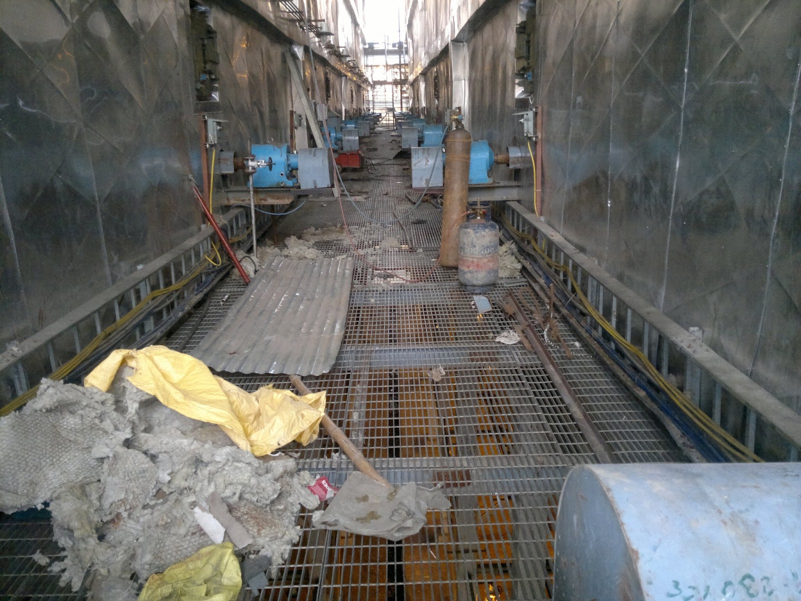
ESP roof top along with HVR transformer , disconnecting switch , insulator housing with heaters,
mechanical interlocks on housing , Rapping mechanism , disconnecting switches etc on view.
P.S If you are looking to earn few legitimate extra money from the comfort of your home then please click on the link given below