Total Pageviews

Wednesday, 30 July 2014

ERECTION SEQUENCE AND PLAN FOR GENERATOR PART-III ( ROTOR INSERTION) CONCLUDING PART. ABC OF THERMAL POWER PLANT.

ROTOR INSERTION PROCESS STARTED.


PLEASE NOTE THE ARRANGEMENTS MADE ON THE ROTOR FOR FIXING LIFTING CEILING FROM EOT CRANE .


PLEASE SEE THE CEILING POSITION WHEN APPROX 50 %ROTOR INSERTED. ALSO LOOK
OUT FOR THE MAX PULLER FITTED BOTH SIDE OF STATOR TO FACILITATE ROTOR INSERTION.


INSERTION PROCESS COMPLETED


P.S If  you are looking to earn few extra money from the comfort of your home then please click on the link given below

LINK 1 - PLEASE CLICK HERE 
LINK 2 - PLEASE CLICK HERE

Wednesday, 23 July 2014

ERECTION SEQUENCE AND PLAN FOR GENERATOR PART-II ABC OF THERMAL POWER PLANT.

Some of the checks are to be carried out before rotor threading is  given below

All electrical tests (dc resistance, IR value and impedance) are carried out on rotor.

Stator is thoroughly cleaned and free from foreign elements like dust, oil/water, spanners, screwdrivers etc.

All electrical tests (dc resistance, IR value) are carried out on stator.

Check healthiness of thermocouple/RTDs of stator core /winding.

Check locking of bolts of clamping plate of stator overhang. Check busbar supports for tightness .

Tightness of compressor blades for axial movement is checked

Check and ensure for locking of all balancing weights to be checked visually / hand feel.

Measure and record male spigot/journal dimensions of rotor on both ends.

Vacuum cleaning of all ventilating holes is carried out and transportation packing & blower protection cover on rotor is removed.

Check through-ness of radial ventilating holes of rotor winding 


Stator is getting  ready for rotor insertion.  please notice the arrangement of maxpuller both sides  and the

piece of rubber solid  laid inside the stator.


Zigs and fixtures are moved and are getting placed in position.


Rotor is brought near to stator for insertion. Please look out for zigs and fixtures


Continued to PART_IIIIP.S

 If  you are looking to earn few extra money from the comfort of your home then please click on the link given below

LINK 1 - PLEASE CLICK HERE 
LINK 2 - PLEASE CLICK HERE

Thursday, 17 July 2014

ERECTION SEQUENCE AND PLAN FOR GENERATOR PART-I ABC OF THERMAL POWER PLANT.

-Foundation Checks  to be carried out. Generally this was done with turbine foundation checks.

- Installing the Foundation Beams and the Sole Plates

-Checking of  High-Voltage Bushings and the Current Transformers for  healthiness.


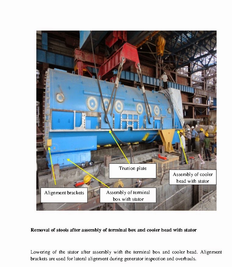
-Positioning of Terminal Box before generator lifting .

-Lower the Generator Frame on Supports after lifting either by EOT crane/ some other method.

-Assembling of Terminal Box, External Seal Welding, Leak Test

-Mounting of Cooling Header, External Seal Welding, Leak Test

-Lower Generator and Perform Preliminary Alignment with the help of jacks .

-Aligning the Foundation Beams with and Bolting them to the Generator

-Installation of Alignment Brackets

-Installing the Primary Water Tank on the top of the generator.

-Installing the Current Connectors

-Prepare the Bottom-Half End Shield Bearings

-Preparing of Rotor for Installation

-Installation of Rotor

-Mounting of Bottom-Half End Shield Bearing, Emplacement of the Rotor

-Lay Rotor Axial to the Generator Frame

-Installation of Air-Gap Seal

-Installation of External Current Connectors (Beginning)

-Alignment of Generator for Release for External Connections

-Measuring the Bearing Clearances

-Pre-assembling of Inner Oil Wipers

-Recording the Dimensional Data of the Seal Ring and the Seal Ring Holder

-Mounting of Compressor

-Mounting the End Shield Bearing Top Halves

-Installation of Inner Oil Wipers

-Alignment of Compressor

-Aligning the Generator and Turbine Couplings

-Grouting of Foundation Beams

-Installation of Gas Distribution System

-Mounting of H2 Cooler

-Final Inspection of the Generator Interior and Mounting the Manhole Covers

-Tensioning of Foundation Anchor Bolts

-Preparation of the Bearing and Seal Oil Systems for Flushing

-Checking Instrumentation and Commissioning Seal Oil System (Beginning)

-Filling the End Shield Bearing Seal Grooves

-Installation of H2 Shaft Seal

-Generator - Leakage Test (Air)

-Final Alignment of Generator to Turbine

-Closing of Bearing Chambers

-Handover of Customer Tools, Winding Up Assembly Site

-Preparation of Exciter Foundation

-Preassembling of the exciter base plate

-Alignment Of the Exciter Coupling to the Generator Coupling

-Grouting the exciter base plate and tensioning of the anchor bolts

-Couple the Exciter shaft and swing check

-Final assembling of the exciter

-Following interface activities to be released as inputs for other system to connect.

-Release for the Oil Line Connection to the End Shield Bearings
( 10 to 12 weeks from start)
-Release for Primary Water Line Connections
( 10 to 12 weeks from start)
-Release for Installing the Foundation Cover
( 14 to 15 weeks from start)
-Release for Cooling Water Line Connections (H2 Cooler)
(16 to 17 weeks from start)
-Release for Bus Bar Interface at the Terminal Bushings
( 21 to 22 weeks from start)
-Release for Connection of Piping to the Exciter Bearing
(24 to 25 weeks from start)
-Release for Cooling Water Line Connection to the Exciter Coolers
(28 weeks from start)
-Release for Coupling of the Steam Turbine 
(28 weeks from start)
The total work is planned for 28weeks to 30th week depending on availability

of materials , civil fronts , availability of EOT crane and other aspects of site.

Out of the above activities one activity is extremely critical considering erection 

angle i.e rotor threading to Generator stator. This require pre-planning of 

material ,manpower and T&P with utmost care.  The same will be described

in PART_II through pictures.

Please observe ceiling protection , support on pedestal etc.

Monday, 7 July 2014

GENERATOR PKG ERECTION PART-IV,( CONCLUDING) LIFTING ARRANGEMENTS OF GENERATOR - ABC OF THERMAL POWER PLANT.

Final part of generator erection with strand jack system is given below through

pictures. Process of genrator erection by strand jack or by crane will be same.
Conitinued to Part -V about erection sequence and other integral system of

Generator.

Saturday, 5 July 2014

GENERATOR PKG ERECTION PART-III, LIFTING ARRANGEMENTS OF GENERATOR - ABC OF THERMAL POWER PLANT.

PART -III

In continuation to my  last blog on erection of generator by strand jack method 

part-ii more pictures now being added to make the erection procedure complete.


Continued to Part-iv 

Friday, 13 June 2014

GENERATOR PKG ERECTION PART-II, LIFTING ARRANGEMENTS OF GENERATOR - ABC OF THERMAL POWER PLANT.


PART- II

Stator lifting by EOT Cranes:-

In earlier days up to 210 /250 MW class the stator is being lifted by two EOT cranes of similar capacity  with lifting beam. EOT cranes main hooks are fitted with the lifting beam and lifting beam main hook is being utilised for lifting stator by using special sling designed for the above purpose. Stator  is placed in the service bay within the approach of EOT crane and unloaded from Trailer / wagon as the transportation method available in the power house. Earlier days a railway line runs  across the service bay. Now a day’s all the stator is coming by high capacity hydraulic Trailer.  Stator is unloaded by hydraulic jacks on temporary supports in the service bay. Fix the trunion plates (04 nos) with the body of the stator after necessary cleaning and blue matching with stator body. This has to be fixed as per the norms because sling will be placed on it. Clean the terminal box and do the blue matching with surface plate. This are the preparatory work for stator lifting. Terminal Box can be placed before stator if there is no other possibilities push it from bottom. Stator is lifted by tandem operation with lifting beam from any of one the crane. This arrangements to be tested before put in actual use. Necessary adjustment to be carried at that time, to avoid any jerk during the operation.


Stator lifting by Portal crane or by strand jack method.:-
Once we are start erecting 500 MW /600 MW /660 MW /800 MW generators the weight of the stator

increases considerable therefore alternative lifting arrangements are thought of . Some of the
utilities  think about the lifting irrespective of loading TG  bay . Otherwise total TG bay need to designed taking stator weight as one of the factor.  Portal crane and strand jack method came as solution. It has been seen availability of Portal is a problem. In my service life we have noticed  that once we need to erect 09 numbers of stator in a year and we have only two portal cranes. Portal dismantling , transportation and re –erecting is 03 to 04 months cycle depends on location of both the sites . We cannot erect all the Generators required by management and to solve this problem stand jack method of stator lifting was adopted. This type of lifting was already popular for boiler drum lifting.
Placement of stator for this type of lifting is very important. The stator need to be placed outside A row column and between transformer bay and A row column. Centre line  of  Generator from TG to be brought and marked for stator placement . No axial movement is possible when stator is placed on foundation. Foundation for jack pads and lifting structures are needed for unloading  the generator  and placed on temporary supports. All other works to be done on generator is same. Stand jack system to be erected by EOT crane and Heavy lift Crawler crane from AB bay and Outside A row. Close co –ordination is required from all quarters as that area includes the area of CW pipelines  for Condenser. Clear approaches is required for heavy duty crane and Hydra cranes.
As the main column pitch distance is less than the stator length swivel arrangement is required in strand jack system. Strand jack system is totally hydraulic and operates slowly it may take  06 to 08 hrs from start to complete the lifting and placement  operation.

Continued to Part -III for more pictorial representation.P.S If  you are looking to earn few extra money from the comfort of your home then please click on the link given below

LINK 1 - PLEASE CLICK HERE 
LINK 2 - PLEASE CLICK HERE

Sunday, 8 June 2014

GENERATOR PKG ERECTION PART-I, GENERAL FEATURES OF GENERATOR WITH PHOTOES - ABC OF THERMAL POWER PLANT.


PART -I

Generator with exciter is the ultimate  output of all the system put together. This is very important item to be installed with turbine system. Generator is the heaviest item to be installed in the power house in single lift. In earlier days generators ( up to 300 MW) class were installed by two EOT crane by using common hook  and tandem operation. But 500 MW onwards this practice was discarded because the structural design and cost required to be done is much higher than the conventional one. Therefore a method was involved to lift the generator which has no bearing with the structural load bearing capacity. Use of Portal crane and more popular is strand jack method gained popularity for lifting stator . We will discuss the same with photographs on later dates. A brief description of 500 MW generator  is given below for new comers.

The two-pole generator uses direct water cooling for the stator winding, phase connectors and bushings and direct hydrogen cooling for the rotor winding. The generator frame is pressure-resistant and gas tight and equipped with one stator end shield on each side. The hydrogen coolers are arranged vertically inside the turbine end stator end shield.

The generator consists of the following components:

• Stator

Stator frame ,End shields ,Stator core ,Stator winding and Hydrogen coolers.

• Rotor

Rotor shaft , Rotor winding, Rotor retaining rings and Field connections

• Bearings


Shaft seals
The following additional auxiliaries are required for Generator operation :
• Oil system , Gas system , Primary water system and  Excitation system.
Cooling System.
-The heat losses arising in the generator interior are dissipated to the secondary coolant (raw water,
condensate etc.) through hydrogen and primary water.
-The hydrogen is circulated in the generator interior in a closed circuit by one multi-stage axial-flow fan arranged  on the rotor at the turbine end. Hot gas is drawn by the fan from the air gap and delivered to the coolers, where it is re-cooled and then divided into three flow paths after each cooler.
-For direct cooling of the rotor winding, cold gas is directed to the rotor end windings at the turbine and exciter ends. The rotor winding is symmetrical relative to the generator centre line and pole axis. Each coil quarter is divided into two cooling zones.
For cooling of the stator core, cold gas is admitted to the individual frame compartments via separate cooling gas ducts. From these frame compartments the gas then flows into the air gap through slots in the core where it absorbs the heat from the core.
The treated water used for cooling of the stator winding phase connectors and bushings is designated as primary water in order to distinguish it from the secondary coolant (raw water, condensate, etc.). The primary water is circulated in a closed circuit and dissipates water is circulated in a closed circuit and dissipates the absorbed heat to the secondary cooling water in the primary water cooler. The pump is supplied with hot primary water from the primary water tank and delivers the water to the generator via the coolers. The cooled water flow is divided into two flow paths .
Stator Frame
 The stator frame consists of a cylindrical centre section and two end shields which are gas-tight and pressure-resistant. The stator end shields are joined and sealed to the stator frame with an O-ring and bolted flange connection. The stator frame accommodates the electricity active parts of the stator, i.e., the stator core and the stator windings.
The stator core is stacked from insulated electrical sheet-steel laminations and mounted in supporting rings over insulated dovetailed guide bars. Axial compression of the stator core is obtained by clamping fingers, pressure plates, and non-magnetic through-type clamping bolts, which are insulated from the core.
The rotor shaft is a single-piece solid forging manufactured from a vacuum casting. Slots for insertion of the field winding are milled into the rotor body. The longitudinal slots poles are obtained. The rotor poles are designed with transverse slots to reduce twice system frequency rotor vibrations caused by deflections in the direction of the pole and neutral axis.
The hydrogen cooler is a shell and tube type heat exchanger which cools the hydrogen gas in the generator. The heat removed from the hydrogen is dissipated through the cooling water. The cooling water flows through the tubes, while the hydrogen is passed around the finned tubes.
The sleeve bearings are provided with hydraulic shaft lift oil during start-up and turning gear operation. To eliminate shaft currents, all bearings are insulated from the stator and base plate, respectively. The temperature of the bearings is monitored with thermocouples embedded in the lower bearing sleeve so that the measuring points are located directly below the BABBITT. Measurement and any required recording of the temperatures are performed in conjunction with the turbine supervision. The bearings have provisions for fitting vibration pickups to monitor bearing vibrations.
Typical 500MW Generator Specification
KW 500,000 ; KVA 588,000 Hz 50 ; R.P.M 3000 ; P.F. 0.85 LAG
Stator  : Volts 21000 ;  Amps 16200 ;  Phase 3; Conn. Y Y ;  Spec. IEC-34
Rotor  :  Amps 4040 ; Volts 340  : Coolant Hydrogen & Water; Gas Pressure 3.5 Kg/cm2 (g)


         Typical 500MW Generator cross section
 Typical 500MW Generator outline drawing and 660 MW  generator. Difference of construction
will be outlined later.
courtesy  BHEL
Continued to PART -II

P.S If  you are looking to earn few extra money from the comfort of your home then please click on the link given below

LINK 1 - PLEASE CLICK HERE 
LINK 2 - PLEASE CLICK HERE