Total Pageviews

Monday, 10 June 2013

MILL PART-II FOR THERMAL POWER STATION.

A few photographs are attached herewith for knowledge so that explanation will be easier to

understand.


Three dimensional photographs of journal assembly.


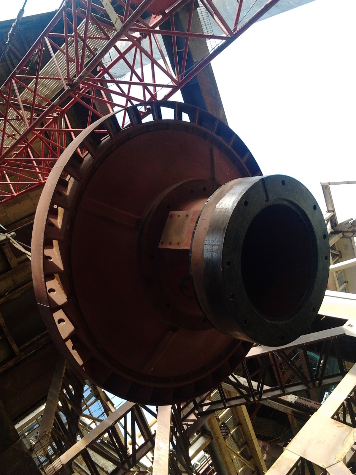
Pre-assembly of Journal is going on at site over mill maintenance platform. All the parts are

coming loose need to be assembled at site before erection.


Assembly of planetary gear box and bowl hub   under progress.


continued to 3rd page.

P.S If  you are looking to earn few legitimate extra money from the comfort of your home then please click on the link given below

LINK 1 - PLEASE CLICK HERE 
LINK 2 - PLEASE CLICK HERE

Sunday, 9 June 2013

MILLS IN A THERMAL POWER STATION PART -I

Since last 91 post i have discussed various aspect of thermal power plant .Mainly i have written

my experience on civil , mechanical , boiler etc. In boiler  I have discussed about structural ,pressure

parts , fans ( id ,fd and pa ) . A few other topics are left behind to discuss. A list now being attached

for ready reference .

1. Mills

2. Ducting

3. insulation

4. piping ( critical and internal)

5. LOS ( Lub oil supply unit)

6. Motorised valves and dampers

7. ESP ( electrostatic precipators)

Control and instrumentation and electrical will be discussed at final stage.

Therefore we are now going to discuss about MILLS . Mill is one of the very essential item

of Boiler. Choice of  MILLS depend on the coal characteristic of the fuel. Number of mills

guide the height of furnace . There are different type of mills , Bowl Mill, Tube mill , Ball

and race mills etc are available in India. There are pressurised Mill and suction type Mill.

I will limit my discussion on BHEL make pressurised Mills . BHEL supplied other mills

also on demand but not on regular basis.


MILL.

Purpose of the Mill is defined below :-

Pulverise the coarse coal into fine powder and transport the same to furnace with the help of PA fan.

Because of pulverisation following advantages are drawn.

1. Better Air - Coal fuel ration.

2. Better flame stability

3. Effective utilisation of carbon.

4. Efficient use of low grade coal in Boiler.

5. Reliable ,safe and flexible operation.

6. All the above will increase the efficiency of the boiler.

GRINDING PROCESS OF MILLS.

Coal are fed from Raw coal feeder ( situated just above the mill on concrete floor) . One end of the

Raw coal feeder is attached with Coal bunker through a coal gate. Raw coal feeder is having a

travelling belt with coal weighing instruments. Coal from travelling belt of raw coal feeder drops

in central feed pipe ( connection between Raw Coal Feeder and Mill). After coal reaches Mill bowl

grinding started and hot air also been given to make the pulverised fuel dried enough to classifier

chamber. The portion of  the coal which cannot be grinded finds its way to mill reject.

Mechanical setting is to be carried out for minimum rejects . Zero rejects also is not good as it

causes excessive wear and tear of the mills. Once the fuel air mixture reaches classifier it will

again classified into two parts one part which heavier part will go back to mill for further grinding

other part will directly go to furnace through four coal pipes and MDV ( Mill discharge valves).

COAL VARIATION IN INDIA.

In my earlier post i have indicated the type coal available in India and other part of the world like

Australia , Indonesia , African countries etc. Now i will detail of Indian coal and variation.

a. Moisture                                                               5 to 30 %

b. Ash                                                                    10 to 55%

c. Volatile matters                                                 12 to 40%

d. Abrasion Index mg/kg                                       60 to 125

e. Hard Groove Index                                            45 to 110  

EFFECTS OF COAL ELEMENT ON MILL CHOICE AND SIZING.

MOISTURE -  More hot air is required to dry the coal particles .

VOLATILE MATTERS- Determine temperature of  Mill outlet and furnace.

ASH              - Grinding element ; coating on rollers etc

HGI               - Grind ability

Calorific Value - Mill sizing.

NOMENCLATURE OF BOWL MILLS FOR  XRP xxxx ( e.g. 1003 /1103)

-  X  stands for Frequency of Power Supply ( 50 Hz  for India )

-  R stands for Raymond ( inventor of Bowl Mill)

-  P stands for Pressurised Mill with Primary Air Fan

- 100/110  stands for Bowl diameter ( inches) ( in case of xrp1003 /xrp 1103)

-  3  stands for Number of grinding Roller.

STANDARD MILL CAPACITY 

MILL SIZE                                        CAPACITY( COAL GRINDING)

XRP 623                                                          18 + TPH

XRP 703                                                          26 + TPH

XRP 763                                                          33.8  TPH

XRP 783                                                          36.5  TPH

XRP 803                                                          39.8  TPH

XRP 883                                                          51 + TPH

XRP 903                                                         54+ TPH

XRP 1003                                                       68 .1 TPH

XRP 1103 HP                                                 91 + TPH


Continued to Part -2

P.S If  you are looking to earn few legitimate extra money from the comfort of your home then please click on the link given below

LINK 1 - PLEASE CLICK HERE 
LINK 2 - PLEASE CLICK HERE


Thursday, 16 May 2013

SEAL AIR FAN , SCANNER AIR FAN ERECTION PLAN SEQUENCE IN THERMAL POWER PLANT

Major Fans like ID ,FD and PA fans are already been discussed in my previous articles. However

two more fans are required to be discussed . The name of the fans are Seal air fans and Scanner air

fans . Scanner air fans are small fans ( Both AC & DC) for supplying cooling air to scanner head.

Scanner heads are placed near the fuel nozzle of every elevation to monitor the fireball of the furnace.

For AC motor driven fans the suction is taken from FD discharge and for DC motor driven fans

( only for emergency suction is taken from atmosphere.) Complete sets of dampers suction &

discharge are attached on the ducts as per requirement . This fans are located rear side of the

boiler operating floor and do not need any civil foundation. It is mounted on structural items

and standard erection procedure can be adopted.

Seal are fans are bigger fans and need civil foundations at Zero metre level. It is generally

located  below the second pass of the furnace. Therefore it can not be erected in the

beginning . It has to follow a sequence to start the civil work. It will be prudent to complete

piling work in the beginning that is before the start of boiler erection and pile cap can also

be completed along main boiler column foundations and if possible first lift can also be

completed the elevation of first lift should be at least 800 mm below the zero metre level. This

will reduce interference problems at later stage as the same area lot of structural work , duct

work , insulation work will be carried out. After completion of first stage civil work the

area to be back filled with soil and compacted to enable movement of heavy duty crane

for boiler work. The area to be again excavated after completion of boiler pressure part

work , Boiler structural work rear side , structural work and hopper work below economiser

and air heater. Requirement of passage  from rear  and sides ceases . The area required to

complete the seal air foundations , duct foundations , compressed air storage vessels for

air heaters etc . This area to be completed in war footing as other mechanical work at that

time will be peak therefore movement of dumper , transit mixer , placement of concrete

pumps etc will be on priority. Zero metre paving can be planned at that time . It is

assumed that all other small foundations etc like dirty oil tank ,pumps etc will be

completed. After completion of civil work mechanical work of equipment erection ,ducting

integral piping work etc   will be carried out.


SEAL AIR FANS

The Seal air fan system consists of the following items:-


Cold Primary air Suction duct.

2 Number of vane type filters & its associated dampers & bleed air lines.

2 Number fans with motors.

Suction Dampers of Seal Air Fan

Discharge Dampers of Seal Air Fan

Discharge Ducts up to Mill Seal air points

Seal Air Fan basically functions as booster fan taking suction from primary air fan discharge (cold 

primary air before AH-A&B) boosting up the air pressure and supplying seal air to various sealing 

points of Bowl Mills.

Seal Air Fan Suction Pressure       : 580 mmwc ( approximately)

Seal Air Fan Discharge Pressure  :  1088 mmwc

Vane filters are provided in the Suction line of the Seal air fan with a provision to continuously bleed any dust laden air in to furnace through Secondary air duct-wind box.

-Foundation checking with reference axis and starting of chipping work on foundations

-Alignment of base plates and bearing pedestals.

-Grouting of base plates and bearing pedestals.

-Pre-assembly of spiral casing

-Alignment of spiral casing with respect to fan centre line.

-Ensure vertical of spiral casing.

-Elevation and horizontal at the parting plane of bottom half of spiral casing at four corners.

-Ensure proper seating of the locating groove in the shaft flange with the impeller.

-Torque tightening of bolts for shaft, conical cover plate, flange and impeller.

-Seating of flange of conical cover plate and impeller

-Fan bearing face out
-Fan bearing clearances

-Fixing of labyrinth seals at expansion and non-expansion end of shaft

-Adjustment of duct supports of suction and discharge ducts to avoid loading / pulling of fan

-Alignment of coupling with motor & fan and ensure tightness of bolts fixing coupling with shaft

TOLERANCES FOR SEAL AIR FAN


Gap between shaft flange and impeller mating face <0.05 mm .

Ensure 80% colour matching between bearing housing and the bearing pedestals.

Horizontal of bearing housing to 0.04 mm / M.

The shaft at fixed end bearing should be levelled to within 0.04 mm / M.


P.S If  you are looking to earn few legitimate extra money from the comfort of your home then please click on the link given below

LINK 1 - PLEASE CLICK HERE 

LINK 2 - PLEASE CLICK HERE


Monday, 13 May 2013

ERECTION SEQUENCE , PLAN ,TOLERENCES OF ID ,FD,PA FANS FOR THERMAL POWER PLANT

SEQUENCES  OF ACTIVITIES OF 'PA' FAN ASSEMBLIES - AXIAL
                 
  MAJOR ACTIVITIES


Foundation: checking of   axis of pockets & elevation
Foundation: Hammer dressing for primary packers
Packers preparation for Impeller Housing Suction Chamber & Diffuser
Shims: Preparation 
Primary packer Blue matching for Impeller. Housing  
Primary packer: Alignment 
Impeller Housing: lower part Erection and levelling
Impeller Hub: Erection  
Suction Chamber: Erection 
Diffuser assembly: Erection  
Intermediate shaft with shaft cover Erection
Measurement of shaft ends and couplings of motor & bearing
Heating & fitting of couplings of motor & fan shaft
Motor Sole plate: Blue matching
Motor: Placement  
Foundation Spring releasing
Levelling of impeller hub
Alignment of Regi-flex coupling
Grouting of primary packers and sole plates
Motor Sole plate: Grouting
Motor Decouple and Trial run
Final alignment after trial run
Impeller blades: Mounting as per serial number & checking
Out let guide van assembly: Erection  
Fitting of actuator assembly accessories & welding
Completion of actuator assembly fitting with setting shaft & checking
Expansion Joints:Between silencer & suction chamber
Silencer assy pre-assemble and welding
Transition piece pre-assemble and welding
Suction hood and Roof pre-assemble & welding
Erection of Total Silencer assy over column 
LOS Base levelling & grouting ( LOS= Lubrication oil supply unit)
LOS pipping fitting, welding & Acid cleaning
LOS pipping erection 
LOS motor decouple and trial run
LOS Oil cooler Hydro test
LOS Oil flushing
Fitting of C & I Instruments over bearing
Box up of Fan assy
Expansion Joints:Between suction chamber & Bearing Housing
Expansion Joints:Between Bearing Housing & Diffuser assemblies
Final checking inside the Fan assembly
Trial run of Fan 
Insulation of Silencer assy and Fan assembly.


SEQUENCES  OF ACTIVITIES OF 'ID' FAN ASSEMBLIES - AXIAL     


                MAJOR ACTIVITIES
Foundation: checking of   axis of pockets & elevation
Foundation: Hammer dressing for primary packers
Packers preparation for Impeller Housing Suction Chamber & Diffuser
Shims: Preparation 
Primary packer Blue matching for Impeller Housing  
Primary packer: Alignment 
Diffuser assembly: Erection  
Impeller Housing: lower part Erection and levelling
Out let guide van assembly: Erection  
Radial seals I and II Erection
Impeller Hub: Erection  
Impeller Housing: Upper part Erection 
Suction Chamber: Erection and welding 
Intermediate shaft with shaft cover Erection
Measurement of shaft ends and couplings of motor & bearing
Heating & fitting of couplings on motor shaft
Fitting of spacer coupling on fan shaft
Motor Sole plate: Blue matching
Motor: Placement  
Impeller blades: Mounting as per sl.no. & checking
Foundation Spring releasing
Levelling of impeller hub
Alignment of Regi-flex coupling (motor with fan)
Grouting of primary packers 
Motor Sole plate: Grouting
Motor Decouple and Trial run
Final alignment after trial run
Fitting of actuator assy accessories & welding
Completion of actuator assy fitting with setting shaft & checking
LOS Base levelling & grouting
LOS pipping fitting, welding & Acid cleaning
LOS pipping erection 
LOS motor decouple and trial run
LOS Oil cooler Hydro test
LOS Oil flushing
Sealing / cooling fan Erection and grouting
Sealing / cooling fan pipping fitting & welding
Sealing / cooling fan trial run for pipe flashing
Fitting of C & I Instruments over bearing
Box up of Fan assembly
Expansion Joints:Between suction chamber & Bearing Housing
Expansion Joints:Between Bearing Hosing & Diffuser assembly
Final checking inside the Fan assembly
Trial run of Fan 
Insulation of Suction camber and Fan assembly.

TOLERANCES OF ERECTION FOR PA FANS


Vertically of the housing. (Tolerance : 0.04 mm / M).   

Axial clearances (C) between bullet and hub / impeller housing and hub (Tolerance : ± 3 mm).

Axial clearances (D) between hub & housing / hub & diffuser core (Tolerance : ± 3 mm).


TOLERANCES OF ERECTION FOR ID FANS

Rotor level / vertically of the housing.(Tolerance : 0.04 mm/M).

Axial clearances (C) between bullet and hub / impeller housing and hub (Tolerance : ± 3 mm).

Axial clearances (D) between hub & housing / hub & diffuser core (Tolerance : ± 3 mm).


P.S If  you are looking to earn few legitimate extra money from the comfort of your home then please click on the link given below

LINK 1 - PLEASE CLICK HERE 

LINK 2 - PLEASE CLICK HERE
Friday, 10 May 2013

ERECTION PLAN FOR ID ,FD AND PA FANS OF THERMAL POWER PLANT

                        SEQUENCES  OF ACTIVITIES OF 'FD' FAN ASSEMBLIES - AXIAL     


             MAJOR ACTIVITIES

-Foundation: checking of   axis of pockets & elevation.
-Foundation: Hammer dressing for primary packers.
-Packers preperation for Impeller. Housing,Suction Chamber & Diffuser

-Primary packer Blue matching for Impeller Housing
-Primary packer: Alignment
-Diffuser assy: Erection
-Impeller Hsg: lower part Erection and levelling
-Impeller Hub: Erection 
-Impeller Housing: upper part Erection
-Suction Chamber: Erection
-Intermediate shaft with shaft cover Erection
-Measurement of shaft ends and couplings of motor & bearing
-Heating & fitting of couplings on motor shaft
-Spacer coupling fitting on fan shaft
-Motor Sole plate: Blue matching
-motor pad blue matching
-Motor: Placement 
-Foundation Spring releasing (after full loading on foundation)
-Levelling of impeller hub
-Alignment of Regibflex coupling (motor and fan)
-Grouting of primary packers of Impeller. Housing,Suction  Chamber. & Diffuser
   
-Motor Sole plate: Grouting
-Motor Decouple and Trial run
-Final alignment after trial run
-Impeler blades: Mounting as per sl.no. & checking
-Fitting of actuator assy accessories & welding
-Completion of actuator assy fitting with setting shaft & checking
-Place ment Expansion Joint obove suction chamber
-Erection of spacer duct and transition duct I &II
-Silencer assy pre-assemble and welding
-Transition piece pre-assemble and welding
-Suction hood and Roof pre-assemble & welding
-Erection of Total Silencer assy & Suc. hood over column
-LOS Base leveling & grouting
-LOS pipping fitting, welding & Acid cleaning
-LOS pipping erection
-LOS motor decoulple and trial run
-LOS Oil cooler Hydro test
-LOS Oil flushing
-Fitting of C & I Instruments over brg
-Box up of Fan assy
-Expansion Joints:Between suction chamber & Brg Hsg
-Expansion Joints:Between Brg Hsg & Diffuser assy
-Final checking inside the Fan assy
-Trial run of Fan
-Insulation of Silerncer assy and Fan assy

Last four activities will be carried out after full and final box up . A few photographs attached.


Basic tolerances of erection  of FD fans.

Colour match between the impeller housing and primary packers (80% minimum).

Rotor level / verticality of the housing. (Tolerance : 0.04 mm / M).

Axial clearances (C) between bullet and hub / impeller housing and hub (Tolerance : ± 3 mm).

Axial clearances (D) between hub & housing / hub & diffuser core (Tolerance : ± 3 mm).

P.S If  you are looking to earn few legitimate extra money from the comfort of your home then please click on the link given below

LINK 1 - PLEASE CLICK HERE 

LINK 2 - PLEASE CLICK HERE

Monday, 6 May 2013

ID,FD,PA FANS FOR BOILER IN THERMAL POWER PLANT PLAN AND BRIEF DESCRIPTION OF FANS

Till my last dispatch I completed the topics of Boiler  structure , Boiler Pressure Parts , Rotary air preheater as major equipment . I have discussed about the plans and erection sequence of the same . Now I will discuss about the fans ( ID , FD and PA) .I am receiving number of e-mails about my dispatches .The questions  are mainly about erection sequences ,clarification of the pictures , suitability of my erection sequence with their project and also about construction equipment. I
request all the readers to read relevant blogs of my 87 dispatches and he will certainly get the answer.
If there is any doubt I will be there to help you out.
Erection sequence of FANs differs with the layout of the plant. According to Mill position side ,rear
or front Fan erection  sequence differs. These are true for FD ,PA fans only. ID Fan is independent of
Boiler erection . An e-mail received from one of the reader about the commencement of civil work for foundations.

First of all we should not consider only fans in that area. There will foundations for Duct support
between Boiler Outlet Flange to ESP , Foundations for Transfer point structures , foundations for
Mill Reject System silos.If foundations require piling then piling and pile cap to be completed
with boiler foundations. If pile cap drawings are not available then pile cap can be  done afterwards.
But then pile cap to be carried out one by one. It has been seen that this type of job leads to delay
due to massive excavation for individual fans.This excavation can only be started when Boiler supporting structure erection completion ( ceiling Girder erection , rear structure erection and air heater  structure erection completion). There should be alternate route for feeding second Pass Pressure Part
material feeding . Civil works for other foundations are to completed with fan foundations . Minimum two heavy duty crane ( 250 MT) capacities will be placed in boiler rear to carry out erection work of Boiler and CHP.Individual fan erection time cycle is around three months to four months. During this time boiler 2nd pass erection ,ducting above air heater , air heaters , Eco handling structures , ESP side inlet nozzle , Gates and dampers of ducting will also be required for erection completion. Therefore this area is very important regarding interfaces are concern and close co-ordination and monitoring are required .

Besides ID ,FD and PA there are two important fans are there one is seal air fan and other is scanner fan. A brief description is given below.
                                                               FANS FOR POWER PLANT


-Supply air for combustion in the furnace and for evacuation of the flue gases formed from the combustion.
-Maintain Balanced Draft inside the furnace.

-Supply air for cooling of equipments working in hot zones.

-Supply air for sealing of gates, feeders & mills bearings etc.

-Air used for combustion is divided into 2 parts:

1.Primary Air
Portion of total air sent through mills to the furnace. This air dries the pulverized coal and transport it to the furnace for combustion.
2.Secondary Air

Large portion of total air sent to furnace to supply necessary oxygen for the combustion.

Types of Fans  :- 1. Axial Fan with two subgroup as i) Impulse ii) Reaction.

2. Radial fans or Centrifugal fan. ( Single suction or double suction).

                                                FD FANS
Supplies secondary air to the furnace through APH to assist in combustion.
Supply total air flow to the furnace except where an independent atmospheric P.A fan is used.
Provides air for sealing requirement and excess air requirement in the furnace.
Axial fan-reaction type with blade pitch control is use in the Pulverized fired boiler(210/250/500 MW).

                                                                    PA FANS


Supply high pressure primary air through APH needed to dry & transport coal directly from the coal mills to the furnace.
Primary air for mills is divided into cold & hot primary air.
Axial fan-double stage-reaction type with blade pitch control is use in the Pulverized fired boiler(210/250/500 MW).

                                                                    ID FANS 

Suck the gases out of the furnace and throw them into the stack by creating sufficient negative pressure in the furnace (5-10 mmwc) in the balanced draft units.
Located in between the ESP and Chimney in the flue gas path.
Radial Fans -double suction-backward curved vane with inlet guide vane(IGV)control and VFD control is use in all boilers

Handles large volume hot dust/ash laden flue gas (temp up to 150 deg C) from furnace and all leakages occurring in the system till the inlet of the fan.
Overcome the pressure drop inside the furnace, Super heater, Re -heater, Economiser, Gas ducting & ESP.
Consumes max. power in all boiler auxiliaries as it handles the large volume and heavy pressure drop of the flue gas.

                                                               SCANNER AIR FANS 


Scanner Air Fan is belong to Centrifugal Fan category.
Supply cooling air to all the flame scanners at different elevations housed in the furnace for sensing flame.
A.C scanner fan boost the pressure of cold secondary air from F.D fan discharge duct in normal operation.
D.C scanner operates only in case of a.c power failure and sucks air directly from the atmosphere.

                                                                     SEAL AIR FANS

Seal Air Fan is also belong to Centrifugal Fan category.
Supply seal air at a pressure higher than system or equipment pressure.
Supply seal air to raw coal feeders, mills bearings, gates etc
Seal fan either boost the pressure of cold secondary air from F.D fan discharge duct or takes air directly from the atmosphere in normal operation.

In my next part i will provide erection sequence of three major fans.


P.S If  you are looking to earn few legitimate extra money from the comfort of your home then please click on the link given below