Total Pageviews

Friday 25 April 2014

TURBINE GENERATOR PKG ERECTION PART-VIII, PLACEMENT OF LP TURBINE- ABC OF THERMAL POWER PLANT.


Part –VIII


Some measurements are taken during assembly of modular IP Turbine.

Journal diameter and corresponding Bearing-bore. Records the value.

Spigot and Recess dimensions of Couplings. Record the value

Out of flatness of coupling Faces (within 0.02 mm concave) & Coupling hole diameter. 

IP Casing Assembly clearances. Record the value and compare with shop result

Alignment of IP Outer Casing w.r.t. Pedestal.

Alignment of Lower Halves of IP Outer and Inner Casing (with Radial & Axial Keys)

Parting Plane gap in Inner Casing after tightening of alternate Bolts (0.02 to 0.03 mm).

Alignment of bearings w.r.t. Rotor. Record shim thickness.

Spring setting of IVCV. Ensure mechanical cleaning of Piping from IVCV to IP Inlet.

Heat tightening of IP Inlet connection & IP Outer Casing

Tightness of bolts at IP Inlet connection

ASSEMBLY OF LP MODULE

In turbine package LP Turbine takes maximum time because the turbine comes in

loose and need to be assembled at site. The job is voluminous and need constant

supervision and measurement.

This assembly can be divided in following sub assemblies

-Assembly of girder and end walls.

-Assembly of LP inner- inner casing and LP inner outer casing lower half.

-Assembly / welding of LP outer casing.

Before starting assembly of LP casing in position, following works are also to be completed :

- Positioning and welding of LP casing centring pin of front and rear side.

- Positioning of key block of LP casing axial keys.
 

- Positioning of all internal of condenser.
 
Two nos. centring pins are to be located below LP front and LP rear pedestal. Necessary pipe
along with two sq. end plates are already provided in the foundation to take the radial load
of the LP casing:
Plumb the centre line from LP front and LP rear pedestal bore on both side over the square
plate of the foundation.
Establish accurate position of the pin and put a punch mark at a required height and mark a
circle and a controlling circle over all the four sq. Plates.
Diameter of the circle must be equal to pin dia. A template equivalent to pin diameter has
to be made for this purpose with about 20 mm thick plate . The template diameter should
be precise.
Make precise hole to match template on all four embedded plate. Ensure that the template
is fitted with minimum clearance and hole centres are perfect as per marking.
Drill hole of about 10 mm diameter on one of square plate of LP front and on one plate of LP rear
for air venting to avoid cracks during welding.
Insert both the pins and carry out the welding as per laid down procedure. Before welding
set correct axial position of the pins.
Insert key block on both the pins and weld their locking ring also. Ensure proper clearances in key
 
block before welding of its locking ring.
Check the welding by DP test.
ASSEMBLY OF GIRDER AND END WALL
Match side matching flange of girder with the surface plate.
Match seating flange of girder where it rests over the LP base plate.
Match and ensure correct positioning of axial key ways of girder.
Colour match side flanges of end wall.
Match and ensure  key block of end wall are parallel.
Place left and right girder with carrier plate, spacer and special packer on LP base plate.
 

Provisionally align and level the girders. Set height of the girder equivalent to machine
centre line maintaining catenaries of the machine.
Assemble locking plate of the front and rear end wall to facilitate its assembly with the
girders.
Assemble front and rear end wall with the girders and ensure perfect parting plane level
during tightening.
Align, level LP outer casing and ensure contact of packers by colour matching/machining of
spacer height.
Install LP casing radial and axial keys.
Assemble inner outer casing axial key blocks on left and right side of girder and dowel them.
Lock with tack welding all the vertical joint bolts.
Put a seal weld run between girder and end wall joint all around except on top face.
Weld girder and end wall parting plane joint with argon welding. Before welding make a V
groove with the help of a chisel and allow the projection of material on surface. Do not
make the groove by grinding.
Do colour matching with a surface plate on all four corner where argon welding have been
carried out.
ASSEMBLY OF LP INNER INNER AND LP INNER OUTER CASING LOWER HALF
Clean the casing and check all the threaded holes.
Do colour matching on all four corners of the casing where it rest over the girder.
Colour match all eight carrier plates of inner casing on both side.
Assemble all carrier plates on girder and do the colour matching with individual carrier
plate.
Prepare Gusset plate of front and rear side with temporary radial keys for fitting in LP inner
casing.
Level and lift LP inner outer casing and assemble/weld both the gusset plates with the help

of some temporary support.

Lower the casing in position over the carrier plates fitted with spacer and special packer.

Provisionally align the casing radial and axial position.

Support the gusset plate with the help of screw jack (about 10-15 tons) on front and rear

side by taking support from condenser stiffeners. Screw jack is to be unscrewed after box-

up.

Adjust the height of the LP inner outer casing as per centre line of the machine and then

level it with the help of instrument.

Ensure that all the eight packers have good contact. Loading of each packer is to be ensured.

Lower the casing by about 2 mm on all the eight packers with the help of shims for

placement of LP rotor to avoid any fouling during placement of rotor.

Fit and weld all gusset plate stiffener pipes except pipe between LP inner outer casing and

condenser. Till neck welding is over do not make any weld connections between condenser

and stiffeners.


LP Turbine placement of a 660MW unit.

HP Turbine with ESV and HPCV , IP Turbine , LP Turbine Lowe casing , Generator ETC is shown

Continued to part -ix

Thursday 10 April 2014

ERECTION OF TURBINE GENERATOR PKG PART-VII, PLACEMENT OF HP MODULE ,IP MODULE- ABC OF THERMAL POWER PLANT.


PART- VII

PLACEMENT OF HP MODULE IN POSITION

Ensure matching of all the four palms of the module where it is resting on the pedestals.

Ensure matching and paralleling of front and rear key block of the HP casing.

Assemble all four jacking screw of HPC and ensure their free movement.


Clean journals and coupling of the HP rotor.
Record journal diameter, coupling hole sizes and spigot diameter of HP rotor.
Lift module in level condition and place it in position by keeping it 3 to 5 mm toward front pedestal side.
During placement of module use temporary packers similar to permanent and additionally support it by four jacking screws.
Ensure load on all four packers with the help of some additional shims if required.
Install temporary radial and axial keys of the casing.
Prepare HP rotor for alignment
PLACEMENT OF IP MODULE IN POSITION
Ensure matching of all the four palms of the module where it is resting on the pedestals.
Ensure matching and paralleling of front and rear key block of IP casing.
Assemble all four jacking screws of IP casing and ensure their free movement. If these jacking screw holes are provided with the bolts from factory then same are to be removed before placement of module.
Clean IP rotor on both sides including coupling and journal.
Record spigot /recess, journal diameter, and coupling hole sizes.
Lift the module in level condition and place the module in position by moving about 7 to 8 mm towards generator end. Use temporary packers for placement of module in position and additionally support the module with jacking screws.
Ensure load on all four packers with the help of some additional shims if required.
Provisionally align the casing on front and rear pedestal bore. Install temporary radial and axial keys of the casing with some shims.
Prepare IP rotor for alignment
Following measurements are carried out during positioning ,alighnment of  HP cylinder module.
Journal diameter and corresponding Bearing-bore.
Spigot and Recess dimensions of Couplings.
Out of flatness of coupling Faces (within 0.02 mm concave) & Coupling hole diameter.
Transverse & Axial alignment of HP Rotor with Bearings & seal bores during its Placement on the Bearings
Centring and axial position of HP casing w.r.t. rotor

Check parallelism during tightening of Breech-nut on HP Inlet Insert.
Assembly of Hydraulic turning Gear with HP Rotor. Check Clearances . Assembly of Emergency Governor.
HP rotor float and Roll check.
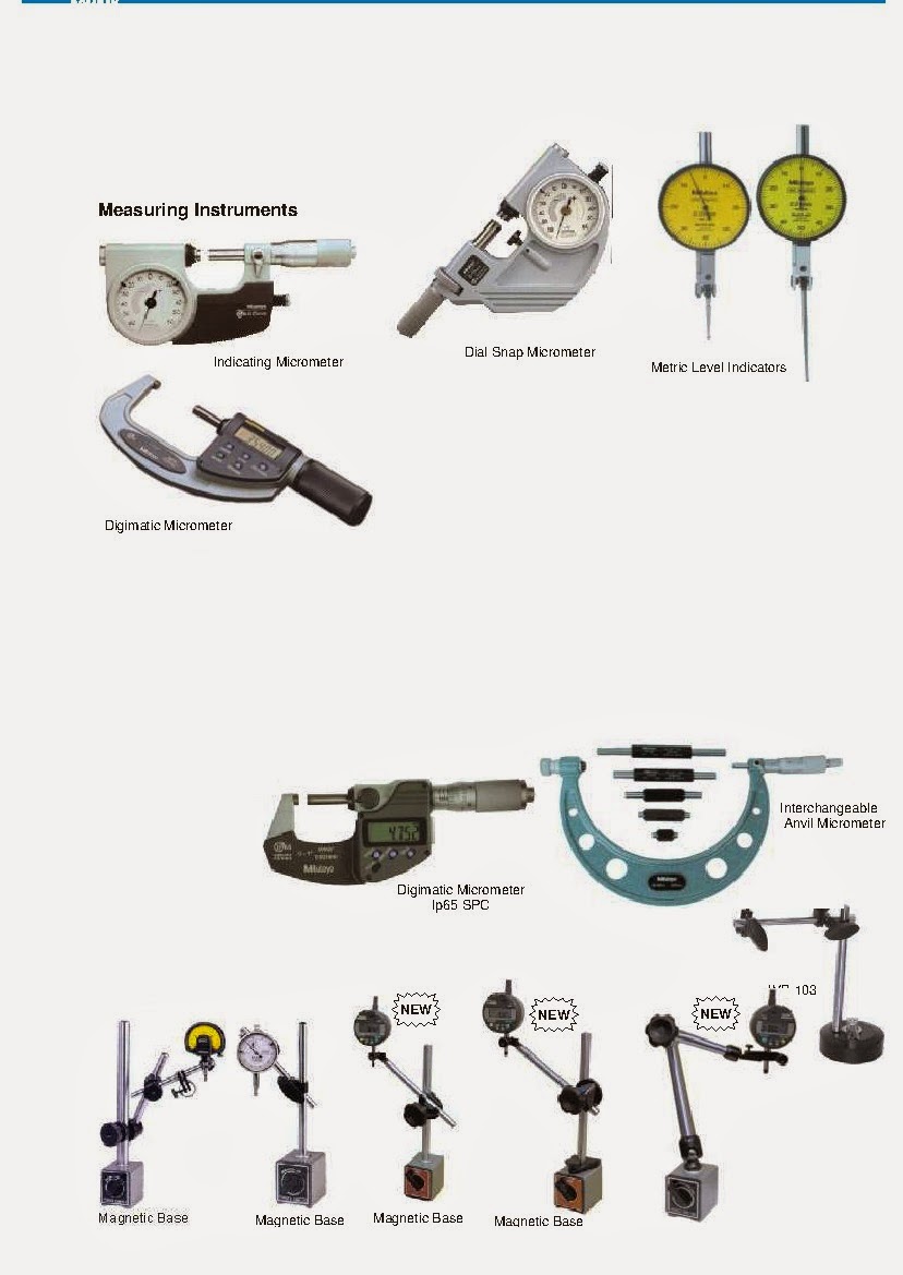
For measurements we use instruments ( calibrated to national standard)  Vernier Caliper, Micrometer , Dial gauge , Straight Edge , Depth Micrometer , Filler Gauge etc.
HP module of 660MW turbine is under placement.

660 MW IP module under placement.
Continued for Part-viii
P.S If  you are looking to earn few legitimate extra money from the comfort of your home then please click on the link given below

LINK 1 - PLEASE CLICK HERE 
LINK 2 - PLEASE CLICK HERE


Sunday 6 April 2014

ERECTION OF TURBINE GENERATOR PKG PART-VI, PEDESTAL, BASE PLATE ERECTION, INSTRUMENTS - ABC OF THERMAL POWER PLANT.


Part –VI

GROUTING OF PEDESTALS AND LP BASE PLATES

 Technical Requirements of Grout material used for turbine pedestal grouting.

Compressive Strength, Non-Shrink  - the compressive strength at 28 days must be not lower than 50 N/mm² .

The early compressive strength at 24 hours must not be lower than 24 N/mm²

- the grout may not shrink. In addition a certain swell-rate is desired (volume increase within 24 hours: atleast 0.2%; according to ASTM C 827-95a). The grout must be water and oil resistant.

The basis of the grout must be cement. It may not contain metallic components and added chloride or other admixtures that may corrode steel.

After adding of water the grout must be in fluid state .In order to improve the flow a high water content should be preferred within the admissible range specified by the manufacturer. The grout should be workable for approximately 45minutes and shall not segregate after grouting.
The specified range of suitable grouting heights must be considered for each application. In case of

a too wide grouting height cracks may occur due to strong heat development. If the grouting height

is too narrow the flow of the grout may be not sufficient and air pockets may form. Where grouting

heights cannot be complied with, a different grout type suitable for the grouting height shall

generally be used. In exceptional cases, a grout may be used for a larger-than-specified grouting


height if a stone aggregate (e.g. quartz) with a specified maximum grain size is

added. The manufacturer's instructions should be followed exactly. In our case
we generally keep the heights between 50 to 70 mm.

The processing instructions and specifications of the grout manufacturer must be complied with. Particularly with regard to the amount of water to be added, the processing temperature, the mixing process, as well as the permissible grouting height. Only drinking water may be used for adding to the grout. Concrete mixers shall be suitably sized .The duration and intensity of the mixing process must also be sufficient .No vibrator shall be used in pouring the grout. Grout should be free  flow (working into place) may be aided by manual.

Fill 3 to 8 mm washed Pea-gravel in all the anchor bolts sleeves. These gravel are necessary to give damping effect to the anchor bolts during operation of the machine.

Seal anchor bolts holes after filling of gravel to avoid any entry of grout metal.  Cap ,tapes etc may be used for sealing .Clean foundation with compressed air. Make shuttering of all the pedestal and LP base plates. Use thick polythene sheet inside the shuttering to give better finish and avoid moisture absorption by shuttering.


Shuttering should be made with maximum care to avoid any leakage of grout concrete. All sides of the shuttering are to be sealed either with some sealing compound or with thick mixture of grout material to avoid leakage of grout material.
Foundation are to be kept wet for about 6 hrs. before grouting.
Non shrinkage cement duly approved by turbine manufacturer is to be used for grouting of the pedestals and base plate. In India we generally use Pagel cement from Pidilite , Conbextra GP 2 from Fosroc , SIKA 214 (ACC) and Five star cement company.
Use fresh stock of the grouting material only and check the strength of the material before use. Every batch of the supply should be tested through cube test if the supply is not of same batch. No material ( grout cement) to be used without testing.
During grouting, the mixture has to be poured from one end only and it has to flow to opposite end to avoid any blockage of air pocket.
Water curing is to be carried out for about 10 days duration.
All anchor bolts are to be stretched minimum after 21 days of grouting.
HP, IP & LP module placement work can be taken up after 24 hours of grouting of the pedestal and base plates.
For individual pedestal and base plate, grout mixture should be poured in one lot only.
It is recommended that supplier representative (technical) is present during grouting of pedestal and LP Base plates and grouting is to be done under their technical supervision.

BRIEF TECHNICAL SPECIFICATION OF BHEL MAKE 500MW (TURBINE)
LOAD ( RATED)                                                                        500 MW
MAX. UNDER VALVE WIDE OPEN (VWO) CONDITION            524.2
THREE CYLINDER REHEAT CONDENSING TURBINE                 500 MW
SINGLE FLOW HP TURBINE WITH 17 REACTION STAGES
DOUBLE FLOW IP TURBINE WITH 12 REACTION STAGES PER FLOW
DOUBLE FLOW LP TURBINE WITH 6 REACTION STAGES PER FLOW
2 MAIN STOP AND CONTROL VALVES ( ESVs and HPCVs)
2 REHEAT STOP AND CONTROL VALVES (IVs and IPCVs)
1 SWING CHECK VALVE IN COLD REHEAT LINE
2 BYPASS STOP AND CONTROL VALVES
EXTRACTION SWING CHECK VALVES :
EXTRACTION-1                                                                               NO VALVE
EXTRACTION-2                              1 SWING CHECK VALVE WITH ACTUATOR
EXTRACTION-3         1 SWING CHECK VALVE WITH ACTUATOR & 1 SWING   
                                    CHECK VALVE WITHOUT ACTUATOR     
EXTRACTION-4.1       2 SWING CHECK VALVE WITH ACTUATOR
EXTRACTION-4.2       2 SWING CHECK VALVE WITH ACTUATOR
EXTRACTION-5
1 SWING CHECK VALVE WITH ACTUATOR & 1 SWING CHECK VALVE WITHOUT ACTUATOR
EXTRACTION-6                                                                         NO VALVE
SPEED (RATED SPEED)                                                             50.0 /S
RANGE                                                                 47.5 TO 51.5 /S
STEAM PRESSURES                                                                 RATED*
INITIAL STEAM                                                                        166.7   BAR
BEFORE 1st HP DRUM STAGE                                                154.4   BAR
HP CYLINDER EXHAUST                                                          44.9     BAR
IP CYLINDER STOP VALVE INLET                                          40.3     BAR
EXTRACTION 6                                                                        44.9          BAR
EXTRACTION 5                                                                        17.5     BAR
EXTRACTION 4                                                                        7.2       BAR
EXTRACTION 3                                                                        2.58      BAR
EXTRACTION 2                                                                        1.329   BAR
EXTRACTION 1                                                                        0.257   BAR
LP CYLINDER EXHAUST                                                          0.1013 BAR
PRESSURE IN SEAL STEAM HEADER (ABOVE ATMOSPHERIC)  35 MBAR

STEAM TEMPERATURES                                                                RATED

INITIAL STEAM                                                                                   536.0
IP CYLINDER STOP VALVE INLET                                                      536.0
HP CYLINDER EXHAUST                                                                    340.0
EXTRACTION 6                                                                                    340.0
EXTRACTION 5                                                                                    413.9
EXTRACTION 4                                                                                    292.1
EXTRACTION 3                                                                                    187.3
EXTRACTION 2                                                                                    128.3
EXTRACTION 1                                                                                    66.5
LP CYLINDER EXHAUST                                                                     46.1
CONTINUED TO PART -VII 

 P.S If  you are looking to earn few legitimate extra money from the comfort of your home then please click on the link given below

LINK 1 - PLEASE CLICK HERE 
LINK 2 - PLEASE CLICK HERE

Wednesday 2 April 2014

ERECTION OF TURBINE GENERATOR PKG PART-V, PEDESTAL, BASE PLATE ERECTION, INSTRUMENTS - ABC OF THERMAL POWER PLANT.


Part –V

PLACEMENT OF LP BASE PLATE,

Clean all the four base plates.

Mark/punch centre line on the base plate as per drawing.

Ensure proper cleaning of base plate on bottom side.

Put identification marks on each base plate to avoid any mistake in positioning of the same.

Do colour matching of all the eight nos. carrier plate on both the faces.

Match LP base plate with the individual carrier plate.

Place all the four base plates in position along with their levelling screws and foundation bolts.

Provisionally align and level all the four base plates.

Assemble protection sheet in the foundation bolt holes.

ALIGNMENT OF PEDESTALS AND LP BASE PLATES


Provisionally align and level all the four pedestals including LP base plates with reference to the earlier marked longitudinal and transverse axis. The elevation reference is to be taken from the already positioned plate for this purpose.
Align and level LP rear pedestal and set the elevation as per machine centre line.

Use piano wire arrangement with micro- meter for centering of pedestal bore and use water level jar for setting of elevation or use any other instruments like dumpy level /total station etc. . Use measuring tape to maintain pitching of the bearing from one pedestal to another. Pedestals are to be set in level condition on both longitudinal and transverse direction. Align and level HP front, HP rear and LP front pedestals. Elevation of the pedestals are to be set as per catenary of the machine considering the half bore error of the pedestal if any.
Align and level, LP base plates. Elevation of LP base plate is to be kept higher than the rear pair of LP base plate in line with catenary of rotor.
After alignment of LP rear pedestal weld the locating rings as mentioned in the drawing.
During welding of locating ring, ensure that there is no movement in the pedestal in any of the direction.
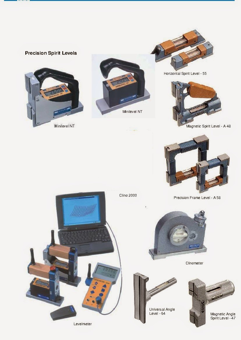
Some of the precision tools used during the erection of steam turbine or any rotating machines is given below. These tools are readily available in India. All the tool manufacturer is having their sales office in India .


Continued to PART-VI

 P.S If  you are looking to earn few legitimate extra money from the comfort of your home then please click on the link given below

LINK 1 - PLEASE CLICK HERE 
LINK 2 - PLEASE CLICK HERE