Total Pageviews

Thursday 27 June 2013

DUCT , INSULATION AND OTHER MISC. ITEMS OF BOILER PART -II

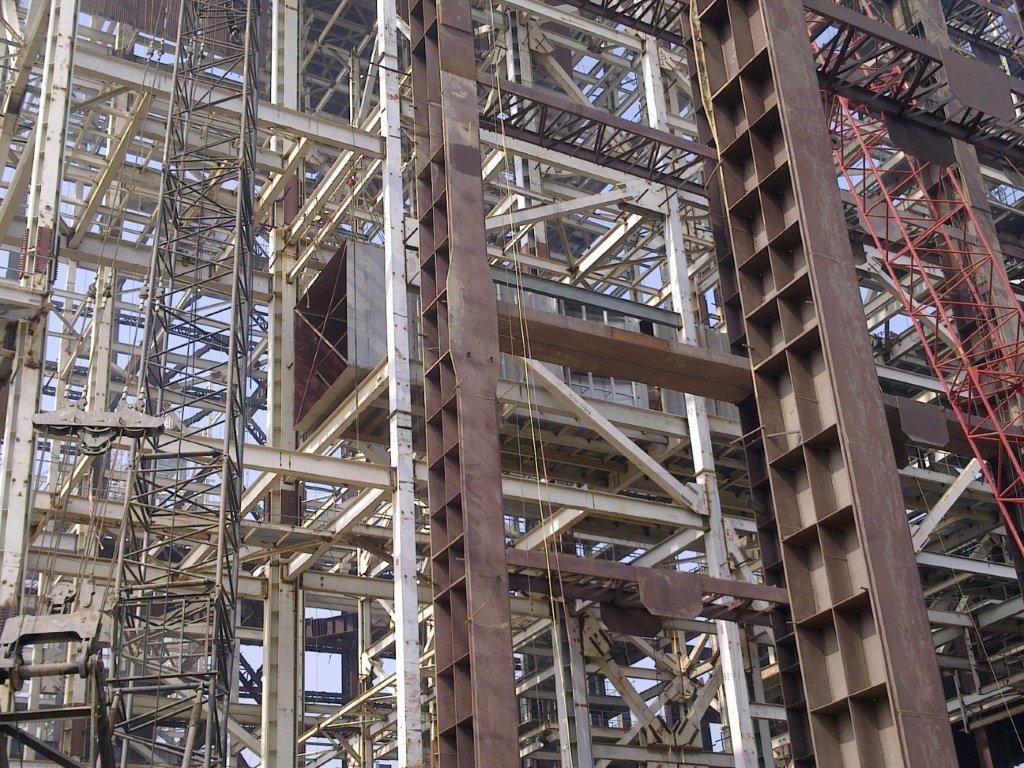
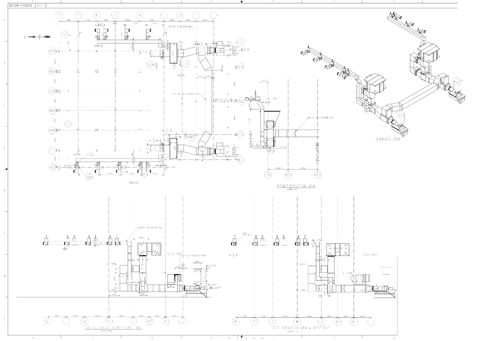
In part -I I have included two drawings and few photographs for understanding. Duct

preassembly job needs to taken up early stage of Boiler erection. Material follow up

need to be done extensively as number of small items are required to be placed . It is

to be kept in mind that flue gas duct will weigh more than the air duct because of plate

thickness is more in flue gas duct due abrasion . Duct can be assembled on flat ground

or raised platform. For bigger duct assembly on ground will be preferred.  However

minimum clearance to be kept for welding of the plates and stiffener component at the

bottom otherwise crane will be required to turn  the same. For 500MW or 660 MW unit

at least 06 to 08 hydras , two number 25MT crawler cranes are required to start assembly

on three beds. For erection crane size will be governed by assembly weight of the Duct.

Special care and checking to be carried for hanger support and bottom support of the

Duct. Expansion joints , Dampers are fitted on the duct on location. Expansion joints

are two types . One is made of metal ( cotton steel) and other is non metal ( made of

special items imported from outside India) . NMEJ is not very popular in India . Except

trying it two three projects utilities were gone back to metallic one.


Pre assembled wind box duct lifted before the lifting of water walls in Boiler.

Tolerances of Ducts.


- After assembly of Duct the  difference between diagonals   +/- 02 mm. to +/- 05 mm.

- Duct reference line to Reference axis ( for example Boiler Axis)  +/- 05 mm.

- Elevation of Ducts w.r.t . bench mark                                            +/- 05 mm.

- End out of squareness of Ducts                                           +/- 02 mm to +/- 05 mm

- Out of roundness of circular duct                                         +/- 02 mm to +/- 05 mm

- Flatness of contact surfaces                                                    03 mm

- Opening Dimensions of Ducts with respect to dampers ( width /height : 05 mm)

- Verticals of both plane dampers  1 mm/M maximum  up to 05 mm.

- Twist or Out of squareness             1mm /M maximum up to 05 mm.

- In case of gates tolerances maximum is up to 10 mm.  Insulation thickness of the duct specially

flue gas duct to be taken care of during site routed tray work and misc. piping work. Welding

work to be completed before starting of insulation duct and few places kerosene test are being

done to detect welding mistake. After assembly of the duct air tightness test were conducted

part by part to identify the leakage and this exercise is very time consuming and time taken but

worth taking at the early stage rather doing it later date by losing generation.


P.S If  you are looking to earn few legitimate extra money from the comfort of your home then please click on the link given below

LINK 1 - PLEASE CLICK HERE 
LINK 2 - PLEASE CLICK HERE


Sunday 23 June 2013

DUCTING , INSULATION AND OTHER ITEMS LIKE MOVS, DAMPERS , OIL UNIT ETC FOR BOILER PART _I

One of the major job in Boiler Erection is ducting of Air and Flue Gas. Around 20% of

Boiler weight comes from ducting and dampers ( excluding support structures). In our

country ducts are fabricated at site and erected. Duct plates manufactured from 6mm to

8 mm steel plates. It requires considerable space to store and to fabricate. Because of its

volume it is not easier to transport. Therefore it is advisable to create a space very near

to boiler for fabrication of Ducting. Ducting job can be subdivided into following groups.


- Prefabrication of ducting to be carried out in two to three places.

- Erection of Ducting inside Boiler area that wind box , FD discharge , Flue gas etc. up to

  Boiler Outlet Flange ( BOF)

- Boiler Outlet Flange to ESP inlet Funnel

- ESP Outlet Funnel to  Chimney through ID Fan.


Out of the above erection of duct inside Boiler is most challenging. It requires pre planning

to execute in a sequence otherwise erection in assembled condition is not possible . A few

areas ducts were erected piece by piece because of its size. There are approach problem in

Boiler . Ducting erection starts with pressure part erection with 03 months lag. During that

time prefabrication starts. Therefore pre fabrication area near boiler to be used for boiler

ducting and to be followed in a sequence  . FD , PA fan ducting to be taken up later as

that place will not be available for erection. Priorities to be given ducting which are

coming at height .

Boiler Outlet flange to ESP inlet ducting is extremely crucial because it comes late. It

will have fixed duration it varies from 60days to 90 days . It is advisable to start

erection from the centre line of the boiler move sideways to extreme end . This will

reduce the requirement of higher capacity of crane. If it starts from end higher capacity

crane more than 250MT class will required.  Please note that area involves lot of

interface with other work like ..CHP gallery , Ash handling structure, Cable and pipe

line structures , civil work of ash trench, Mill rejects Silo. etc. It has also interface

with suction chamber erection of FD and PA. All these need to be coordinated to

erect these ducts.

ESP outlet funnel to ID fan inlet and ID Fan outlet to Chimney does not have any

interface with other work and can be started at the earliest if foundations and material

are available. These ducts specially after ID fan are very big ducts and need to be

fabricated near erection point. Only point to be taken into account is completion of

Chimney outer shell otherwise debris from the top may disturb this erection.

A few photographs are attached herewith.


Above picture shows duct fabrication is going on by side of the ESP .


Duct erection inside boiler area is under progress.


Plan view of ducting from BOF to chimney.


PA fan discharge ducting../


to be continued.


P.S If  you are looking to earn few legitimate extra money from the comfort of your home then please click on the link given below

LINK 1 - PLEASE CLICK HERE 
LINK 2 - PLEASE CLICK HERE

Wednesday 19 June 2013

MILL PART IV TOLERANCES AND OTHER ERECTION ISSUES IN A THERMAL POWER STATION

Fasteners required to be tightened ( as per manufacturer's torque value) in a Mill.

-Sole plate to foundation anchor bolt

-Side assembly to mounting plate foundation anchor bolt

-Gear box base to sole plate

-Bowl hub to gear box super bolt

-Side assembly to separator body

-Separator body to separator top

-Bowl extension ring

-Bowl clamping ring

-Vane wheel assembly

-Separator top to valve out let

-Valve out let to Mill Discharge Valve

-Mill Discharge Valve  to valve adaptor

-Journal head to trunnion shaft

-Journal shaft to journal head

-Keeper plate to journal shaft

-Journal liner to journal shaft

-Journal opening cover to separator body

-Journal spring to JOC


As these bolts or nuts are to be torqued tightened it is necessary to 
about the torque wrench available in the Market. There are three types of torque wrenches

available in the market e.g pneumatic( driven by compressed air),electric ( driven by electric

power) and  manual. For Mill we prefer manual wrenches as variance are more.

Standard Tolerances for Mill erection job

Foundation: ( Mill , motor , gear box , Lubrication unit )

- Disposition with respect to Boiler axis ( Tolerances +/- 5 mm )

- Elevation of Top of foundation after chipping of loose concrete ( Tolerances +/- 10 mm)

- Center line of foundation bolt hole with respect to foundation center line ( Tolerances +/- 2 mm)

- Diagonals of bolt hole center ( Tolerance +/- 5 mm)

- Depth of foundation hole ( Tolerance +/- 10 mm )

- Spacing between the pockets ( Tolerance +/- 2 mm)

It is to be noted before casting of Mill foundation and other important rotating machine foundations

like ID ,FD ,PA etc . A cross check should be done with civil drawing and equipment supplier

drawing . There is chance of mistake due to various reasons and once casting is over it may take

lot of time to rectify.

BASE / SOLE PLATES

-Leveling of  Base Plates for Gear Box ( Tolerance 0.1 mm/M)

-Leveling of mill air side housing sole plates ( Tolerance 0.2 mm/M)

- Grouting Gap between base plates and foundation ( Tolerance 40 +/- 10 mm)

- Leveling of Motor Base within +/_ 0.05 mm/M

-


P.S If  you are looking to earn few legitimate extra money from the comfort of your home then please click on the link given below

LINK 1 - PLEASE CLICK HERE 
LINK 2 - PLEASE CLICK HERE

Wednesday 12 June 2013

MILL PART -III ERECTION SEQUENCE OF MILL IN THERMAL POWER STATION


A few pictures were posted to help construction workmen about the Mill equipment. The

Mill is having planetary gear box and is for a super thermal power project. The Mill is

xrp 1103. However for lower capacity unit worm gear box are used instead of planetary

gear box. In case worm gear box erection of worm gear box in a 500 MW unit becomes

slight problem. The weight of worm gear box for BHEL make XRP 1003 is nearly 67t

which very difficult lift and place in position because feeder floor which is on 19M

height. Clearance of 18.5 M is available for lifting . Therefore it is very difficult to

gear box in the foundation because of foundation restriction. Please take care before

hand .Please note due space constraints cranes size more than 100t/150t is not feasible

to place.


ERECTION SEQUENCE OF MILL WITH PLANETARY GEAR BOX.


-Foundation:Checking
-Foundation: cheeping for grouting
-Primary packers Preparation for sole plate and mounting plate
-Sole plate & Mounting Plates alignment, elevation, and flatness.
-Grouting of sole plate and mounting
-Planetary gear box installation
-Mill side assembly installation,aligned and orientated .
-Concentric checking of gear box with side assembly
-Dowel pin installation gearbox with sole plate
-Bowl & bowl hub installation
-Seperator body erection,aligned and orientated
-Ceramic cone erection with support tube
-Seperator top erection,aligned and orientated
-Airport assembly segment erection & welding
-Bull ring segment erection
-Mill discharge valve,valve outlet & valve adapter erection
-Center feed pipe upper & lower erection and welding
-Inverted cone erection
-Super bolt tightening and bowl hub insulation
-Scraper assembly erection.
-Bowl hub air seal erection upper & lower
-Grinding roll installed on journal shaft
-Journal roller assemblies erection
-Journal opening cover erection
-Journal spring pre-load set.
-Spring Assembly to journal head gap set
-Coal sampling platform
-Seal air piping  erection for MDV( Mill Discharge Valve)
-Seal air piping  erection for journal roller assembly
-Coupling installation on motor shaft
-Motor alignment with gear box
-LOS Piping fitting
-LOS Piping welding
-LOS Piping acid cleaning
-Hydro test of oil cooler
-Planetary gearbox & lube system flushing
-Trial run of motor
-Motor Final alignment
-Mill motor coupling guards installation.
-Trial run of mill
-Ring to roll gap setting.


A ceramic tiles lined inner cone without centre pipe.


to be continued.

P.S If  you are looking to earn few legitimate extra money from the comfort of your home then please click on the link given below

LINK 1 - PLEASE CLICK HERE 
LINK 2 - PLEASE CLICK HERE